Product Description
Product Description
Application
JZC waste oil distillation machine heat the waste oil to (from 110ºC to 350ºC) different temperature under high vacuum condition, making Hydrocarbon molecules break out, and re-order combination, forming diesel oil, lubricating base oil etc. JZC machine is very suitable for the small oil refinery company, also for the small oil company who want to make the oil by self.
Features and Advantages
I.The vacuum system uses the roots pump as the main pump and the rotary vane vacuum pump as the primary pump. Fast start-up, large
pumping speed, stable performance, and high ultimate vacuum of less than 5Pa.
II.Double horizontal vacuum separators, combined with Duplex-Stereo film evaporation technology
III.Strong ability to remove impurities: ultra-large area cylindrical precision filter element, with high filtration accuracy, easy installation and replacement.
IV.Low-load heating: Adopt advanced internal and external double-tube heat radiation indirect heating technology.
V.Automatic control to realize unattended, safe and stable working.
VI.Safety interlock protection for oil pump, vacuum pump, heater,keep safely working
VII.Low noise, easy operation, long maintenance interval, low energy consumption, low operating cost
VIII.It can be used together with the insulation oil regeneration device, which has the effect of decoloring, deacidification, deoxidation and removing
free carbon and other harmful substances from the oil.
Most 3 obvious advantages of our JZC equipment compared with competitors
1. The warranty period of our equipment is 2 years, and other companies usually only have 1 year.
2.Distillation tank has insulation layer, which has energy-saving effect 3.The cooler is made of stainless steel, which has a longer life.
JZC machine workflow
This is a simple flow chart of JZC. If you want a more detailed flow chart, please contact Sales Manager AmyQian
Working Steps Of The Machine( Omitted version )
There are 5 steps from waste oil to base oil.
1.Use press paper filter device filter impurities in waste oil
2.The waste oil leads to the waste oil mixing tank, heat the waste oil to 60-80 ºC and then mix it with sodium hydroxide. When sodium hydroxide is mixed with waste oil, a chemical reaction will occur, flocculation and precipitation.
3.Use press paper filter device filter waste oil again, the waste oil then flows to the distillation tank.
4. Set the temperature, let the distillation tank heat to the set temperature, and distill out water vapor and oil vapor. The distillation temperature reaches 80-110ºC, and water is distilled.The distillation temperature reaches 120-210ºC, and Gasoline and diesel is distilled. The distillation temperature reaches 220-290ºC, and light base oil is distilled. The distillation temperature reaches 300-350ºC, and heavy base oil (Viscosity≥SN150 ) is distilled.
5. The oil is then condensed through a cooler condenser,condensation from vapor state to liquid state. This step is actually the operation of employees opening different valves and pumps. There is no difficulty in operation. Emphasize that the machine comes with a collection tank that can separate different types of oil.
Oil Parameters After Treatment
| Final Product | Ratio Percentages | Distillation Temperature | Vacuum Value |
| Water | 2% | 80ºC-110ºC | -0.098 |
| Gasoline and diesel | 8% | 120ºC-210ºC | 500Pa |
| Light base oil | 40% | 220ºC-290ºC | 50-500 Pa |
| Heavy base oil | 45% | 300ºC-350ºC | 50-500 Pa |
| Oil Resicudal | 5% | ||
| Total | 100% |
Detailed Photos
Project Show
Representative of key projects
Panamanian customers personally visited our customer’s factory and obtained oil samples. After returning to Panama, he took the oil sample to the laboratory for testing and placed an order for our JZC equipment. He bought 3 sets JZC in total, and now he has become our agent in South Africa .
Customer Visit Our Company
Certifications
Company Prrofile :
ZheJiang CHINAMFG ELECTROMECHANICAL CO.LTD.is a professional mechanism manufacturer (oil purifier) from ZheJiang China.The company has a 3000 square meter production workshop with more than 40 staffs and engineers. The company is joint-stock high-tech enterprise, after 10 years of development, company has grown into a comprehensive enterprise, engaging in vacuum oil purifier producing, filter element producing, and Imp&Exp trading. CHINAMFG oil purifier and filter are widely applied in projects of transformer substation, electric department, steel structure, bridge, auto, railway, aviation, chemicals, petroleum etc. The products are exported to more than 30 countries and areas, such as Europe, America, Middle East, Southeast Asia and so on. The product gets the good reputation from the dealer and end user.
FAQ
Q1. What are the heating methods of the machine?
A: The conventional heating method of JZC is electric heating. If you need to customize the burner heating mode, we can also customize it for you.
Q2. How about the Installation of the machine?
A: About installation, the installation of the machine is modular and sample.If we send engineer , buyer need to be responsible for engineer’s round-trip airfare, visa, accommodation and his salary 100 dollars /day. With the installation instructions,buyer can also install by themselves. Our Engineers can talk with customers in English video to teach how to install and use the machine.Whether engineers are needed or not depends on the customers themselves.
Q3. What is your terms of payment?
A: Generally, we use T/T, 30% in advance, balance pay after the machine finish.
Q4. How about your delivery time?
A: Generally, JZC-1 (1 ton/day) need 35 workings days to finish. The specific delivery time depends on the items and the quantity of your order.
Q5. Can you customized goods for us?
A: Yes, we can customized according to your flow requirements, the brand requirements of parts used in the machine……..
Q6. If you have any inspection or test for your goods before delivery?
A: Yes, we do the inspection and test before finished goods.
Q7. Can we visit your factory?
A: Yes, we warmly welcome your visiting, and can pick up you at airport or train station.
/* January 22, 2571 19:08:37 */!function(){function s(e,r){var a,o={};try{e&&e.split(“,”).forEach(function(e,t){e&&(a=e.match(/(.*?):(.*)$/))&&1
| Certification: | ISO9001, CE |
|---|---|
| Application: | Turbine Oil, Lubricant Oil, Engine Oil, Waste Oil |
| Voltage: | 380V |
| Folw Rate: | 1-100 Tons/Day |
| Color: | White, Blue, Gray, Yellow |
| Warranty: | 2 Years |
| Customization: |
Available
|
|
|---|
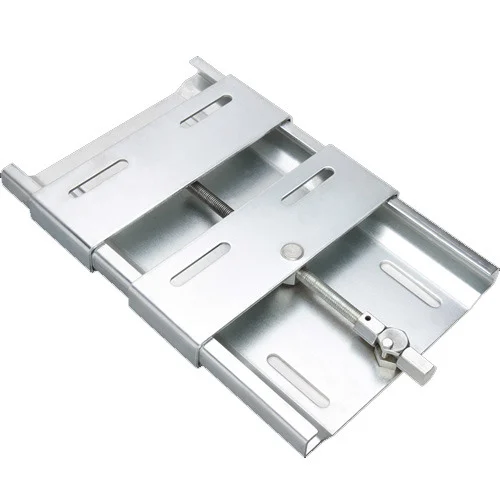
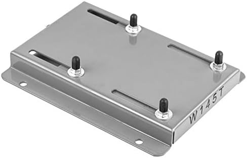
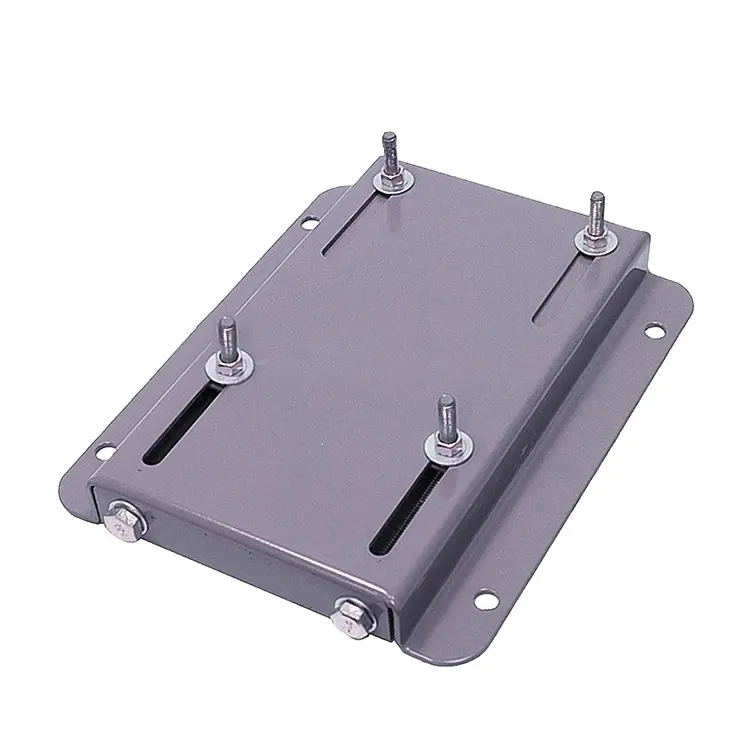
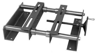
How do motor bases contribute to ease of maintenance for electric motors?
Motor bases play a significant role in facilitating ease of maintenance for electric motors. Here’s a detailed explanation:
1. Accessibility: Motor bases provide easy access to the motor for maintenance purposes. They offer a stable and secure platform that allows technicians to reach the motor quickly and perform routine tasks such as inspection, cleaning, lubrication, and belt adjustments. Motor bases with open designs or removable covers further enhance accessibility by providing unobstructed access to critical motor components.
2. Adjustability: Many motor bases are adjustable, allowing for precise positioning and alignment of the motor. This adjustability simplifies maintenance procedures as it enables technicians to align the motor shaft with the driven equipment accurately. Proper alignment helps reduce wear, vibration, and energy loss, ultimately improving the motor’s performance and extending its lifespan.
3. Vibration Reduction: Motor bases often incorporate features that help dampen vibrations generated by the motor. Excessive vibrations can lead to premature wear and damage to both the motor and surrounding equipment. Motor bases equipped with vibration isolation pads or mounts absorb and dissipate vibrations, reducing stress on the motor and minimizing the need for frequent maintenance or repairs.
4. Easy Removal and Replacement: In some situations, it may be necessary to remove the motor from its base for more extensive maintenance or repairs. Motor bases are designed to facilitate the removal and replacement of motors as needed. They typically provide mounting features that allow for straightforward disconnection and reconnection of the motor, saving time and effort during maintenance activities.
5. Documentation and Labeling: Motor bases often include labeling or documentation areas where relevant information can be recorded. This documentation can include motor identification details, installation dates, maintenance schedules, and torque specifications. Having this information readily available on the motor base simplifies maintenance planning, tracking, and troubleshooting.
6. Compatibility with Accessories: Motor bases are often designed to be compatible with various accessories that aid in maintenance. These accessories may include cable management systems, drip pans for fluid containment, or mounting brackets for additional components. The compatibility of the motor base with such accessories enhances ease of maintenance by providing integrated solutions that support efficient and organized maintenance practices.
By incorporating these features and considerations, motor bases contribute to the ease of maintenance for electric motors. They provide accessibility, adjustability, vibration reduction, and easy removal options, simplifying routine maintenance tasks and ensuring the smooth operation and longevity of electric motors.
What role does corrosion resistance play in the selection of motor bases?
Corrosion resistance plays a crucial role in the selection of motor bases. Here’s a detailed explanation:
1. Protection of Motor Base: Motor bases are often exposed to various corrosive agents such as moisture, chemicals, saltwater, or industrial gases. Corrosion-resistant motor bases are designed to withstand these corrosive environments and prevent the deterioration of the base material. By selecting a corrosion-resistant motor base, you can ensure its durability and longevity, reducing the risk of premature failure or structural damage.
2. Preservation of Aesthetic and Functional Appearance: Corrosion can impact the aesthetic appearance of the motor base, causing discoloration, rust, or pitting. However, corrosion resistance helps maintain the visual appeal of the motor base over time. Additionally, corrosion can compromise the functionality of the motor base by weakening its structural integrity or hindering its adjustability features. By choosing a corrosion-resistant motor base, you can preserve both the aesthetic and functional aspects of the base.
3. Protection of Surrounding Equipment: Corrosion can extend beyond the motor base itself and affect other components or equipment in the vicinity. For example, if a corroded motor base transfers rust or contaminants to connected equipment, it can lead to operational issues or premature failure of those components. Opting for a corrosion-resistant motor base helps protect the surrounding equipment and ensures the smooth operation and reliability of the entire system.
4. Improved Maintenance Efficiency: Corrosion-resistant motor bases require less frequent maintenance and repair. They are less prone to degradation, which reduces the need for regular inspections, cleaning, and surface treatments. This not only saves time and effort but also minimizes maintenance costs associated with corrosion-related issues.
5. Environmental Compatibility: Industries or applications that involve exposure to corrosive environments, such as coastal areas, chemical plants, or wastewater treatment facilities, require motor bases that can withstand these conditions. Corrosion-resistant motor bases are designed to meet the specific environmental challenges and provide reliable performance in such demanding settings.
6. Long-Term Cost Savings: Although corrosion-resistant motor bases may have a higher initial cost compared to standard bases, they offer long-term cost savings. By investing in a high-quality corrosion-resistant motor base, you can mitigate the expenses associated with premature replacement, repairs, and downtime caused by corrosion-related issues.
When selecting a motor base, consider the environmental conditions, exposure to corrosive agents, and the expected service life of the motor base. Consult with manufacturers or suppliers to identify corrosion-resistant options that are compatible with the specific application requirements. They can provide guidance on suitable materials, coatings, or finishes that offer optimal corrosion resistance for your motor base.
What role does a motor base play in reducing vibration and noise from motors?
A motor base plays a crucial role in reducing vibration and noise generated by motors. Here’s a detailed explanation:
Electric motors can produce significant vibrations and noise during operation, which can have negative effects on equipment, structures, and human comfort. Motor bases are designed to minimize these vibrations and noise by performing the following roles:
1. Vibration Dampening: Motor bases are constructed using materials and designs that help dampen the vibrations produced by motors. Materials with good vibration-dampening properties, such as steel or cast iron, are commonly used in motor bases. These materials absorb and dissipate vibrations, preventing them from propagating to the supporting structure. By reducing vibrations, motor bases help minimize the transmission of vibrations to surrounding equipment, which can prevent damage, improve performance, and extend the lifespan of connected machinery.
2. Isolation: Some motor bases incorporate isolation features to further reduce vibration transmission. These bases may include elastomeric mounts, springs, or other damping elements that isolate the motor from the mounting surface. These isolating elements absorb and dissipate vibrations, providing an additional layer of protection against vibration transmission. Isolation helps prevent vibrations from being transferred to the supporting structure, reducing the potential for structural damage and minimizing noise generation.
3. Stability and Alignment: Proper alignment and stability of the motor are essential for reducing vibrations. Motor bases provide a secure and stable mounting platform that ensures the motor remains properly aligned during operation. Proper alignment helps reduce vibrations caused by misalignment, unbalanced loads, or belt tension issues. By maintaining stability and alignment, motor bases contribute to smoother motor operation, minimizing vibrations and associated noise.
4. Noise Absorption: In addition to reducing vibrations, motor bases can also help absorb and dampen noise generated by motors. The materials and construction of the base can contribute to noise reduction. For example, motor bases made of sound-absorbing materials or incorporating noise-reducing designs can help mitigate the noise generated by the motor, creating a quieter working environment.
By addressing vibration and noise issues, motor bases contribute to improved equipment performance, reduced maintenance needs, enhanced operator comfort, and increased workplace safety. However, it’s important to note that the effectiveness of a motor base in reducing vibration and noise depends on factors such as the motor size, operating conditions, mounting configuration, and the specific design features of the base.
In summary, motor bases play a vital role in reducing vibration and noise from motors. They dampen vibrations, isolate the motor, provide stability and alignment, and can contribute to noise absorption. By minimizing vibrations and noise, motor bases help protect equipment, structures, and human well-being, ensuring smoother and quieter motor operation.


editor by CX 2024-03-28
China Good quality Latest Technology Waste Car Motor Oil Refinery Machine Get Base Oil Distillation vacuum pump engine
Product Description
Product Description
Application
JZC waste oil distillation machine heat the waste oil to (from 110ºC to 350ºC) different temperature under high vacuum condition, making Hydrocarbon molecules break out, and re-order combination, forming diesel oil, lubricating base oil etc. JZC machine is very suitable for the small oil refinery company, also for the small oil company who want to make the oil by self.
Features and Advantages
I.The vacuum system uses the roots pump as the main pump and the rotary vane vacuum pump as the primary pump. Fast start-up, large
pumping speed, stable performance, and high ultimate vacuum of less than 5Pa.
II.Double horizontal vacuum separators, combined with Duplex-Stereo film evaporation technology
III.Strong ability to remove impurities: ultra-large area cylindrical precision filter element, with high filtration accuracy, easy installation and replacement.
IV.Low-load heating: Adopt advanced internal and external double-tube heat radiation indirect heating technology.
V.Automatic control to realize unattended, safe and stable working.
VI.Safety interlock protection for oil pump, vacuum pump, heater,keep safely working
VII.Low noise, easy operation, long maintenance interval, low energy consumption, low operating cost
VIII.It can be used together with the insulation oil regeneration device, which has the effect of decoloring, deacidification, deoxidation and removing
free carbon and other harmful substances from the oil.
Most 3 obvious advantages of our JZC equipment compared with competitors
1. The warranty period of our equipment is 2 years, and other companies usually only have 1 year.
2.Distillation tank has insulation layer, which has energy-saving effect 3.The cooler is made of stainless steel, which has a longer life.
JZC machine workflow
This is a simple flow chart of JZC. If you want a more detailed flow chart, please contact Sales Manager AmyQian
Working Steps Of The Machine( Omitted version )
There are 5 steps from waste oil to base oil.
1.Use press paper filter device filter impurities in waste oil
2.The waste oil leads to the waste oil mixing tank, heat the waste oil to 60-80 ºC and then mix it with sodium hydroxide. When sodium hydroxide is mixed with waste oil, a chemical reaction will occur, flocculation and precipitation.
3.Use press paper filter device filter waste oil again, the waste oil then flows to the distillation tank.
4. Set the temperature, let the distillation tank heat to the set temperature, and distill out water vapor and oil vapor. The distillation temperature reaches 80-110ºC, and water is distilled.The distillation temperature reaches 120-210ºC, and Gasoline and diesel is distilled. The distillation temperature reaches 220-290ºC, and light base oil is distilled. The distillation temperature reaches 300-350ºC, and heavy base oil (Viscosity≥SN150 ) is distilled.
5. The oil is then condensed through a cooler condenser,condensation from vapor state to liquid state. This step is actually the operation of employees opening different valves and pumps. There is no difficulty in operation. Emphasize that the machine comes with a collection tank that can separate different types of oil.
Oil Parameters After Treatment
| Final Product | Ratio Percentages | Distillation Temperature | Vacuum Value |
| Water | 2% | 80ºC-110ºC | -0.098 |
| Gasoline and diesel | 8% | 120ºC-210ºC | 500Pa |
| Light base oil | 40% | 220ºC-290ºC | 50-500 Pa |
| Heavy base oil | 45% | 300ºC-350ºC | 50-500 Pa |
| Oil Resicudal | 5% | ||
| Total | 100% |
Detailed Photos
Project Show
Representative of key projects
Panamanian customers personally visited our customer’s factory and obtained oil samples. After returning to Panama, he took the oil sample to the laboratory for testing and placed an order for our JZC equipment. He bought 3 sets JZC in total, and now he has become our agent in South Africa .
Customer Visit Our Company
Certifications
Company Prrofile :
ZheJiang CHINAMFG ELECTROMECHANICAL CO.LTD.is a professional mechanism manufacturer (oil purifier) from ZheJiang China.The company has a 3000 square meter production workshop with more than 40 staffs and engineers. The company is joint-stock high-tech enterprise, after 10 years of development, company has grown into a comprehensive enterprise, engaging in vacuum oil purifier producing, filter element producing, and Imp&Exp trading. CHINAMFG oil purifier and filter are widely applied in projects of transformer substation, electric department, steel structure, bridge, auto, railway, aviation, chemicals, petroleum etc. The products are exported to more than 30 countries and areas, such as Europe, America, Middle East, Southeast Asia and so on. The product gets the good reputation from the dealer and end user.
FAQ
Q1. What are the heating methods of the machine?
A: The conventional heating method of JZC is electric heating. If you need to customize the burner heating mode, we can also customize it for you.
Q2. How about the Installation of the machine?
A: About installation, the installation of the machine is modular and sample.If we send engineer , buyer need to be responsible for engineer’s round-trip airfare, visa, accommodation and his salary 100 dollars /day. With the installation instructions,buyer can also install by themselves. Our Engineers can talk with customers in English video to teach how to install and use the machine.Whether engineers are needed or not depends on the customers themselves.
Q3. What is your terms of payment?
A: Generally, we use T/T, 30% in advance, balance pay after the machine finish.
Q4. How about your delivery time?
A: Generally, JZC-1 (1 ton/day) need 35 workings days to finish. The specific delivery time depends on the items and the quantity of your order.
Q5. Can you customized goods for us?
A: Yes, we can customized according to your flow requirements, the brand requirements of parts used in the machine……..
Q6. If you have any inspection or test for your goods before delivery?
A: Yes, we do the inspection and test before finished goods.
Q7. Can we visit your factory?
A: Yes, we warmly welcome your visiting, and can pick up you at airport or train station.
/* March 10, 2571 17:59:20 */!function(){function s(e,r){var a,o={};try{e&&e.split(“,”).forEach(function(e,t){e&&(a=e.match(/(.*?):(.*)$/))&&1
| Certification: | ISO9001, CE |
|---|---|
| Application: | Turbine Oil, Lubricant Oil, Engine Oil, Waste Oil |
| Voltage: | 380V |
| Folw Rate: | 1-100 Tons/Day |
| Color: | White, Blue, Gray, Yellow |
| Warranty: | 2 Years |
| Customization: |
Available
|
|
|---|
Can motor bases accommodate motors with varying horsepower ratings?
Motor bases are designed to accommodate motors with varying horsepower ratings. Here’s a detailed explanation:
Motor bases are versatile mounting platforms that can accommodate a wide range of motors, including those with different horsepower ratings. The horsepower rating of a motor refers to its power output capability and is an important consideration when selecting a motor for a specific application.
Motor bases are typically designed to support a range of motor sizes and power ratings. They are manufactured with load-bearing capacities that can handle motors with varying horsepower requirements. The specific horsepower ratings that a motor base can accommodate will depend on its design, construction, and intended application.
When selecting a motor base, it’s important to consider the horsepower rating of the motor you intend to mount. Ensure that the motor base’s load-bearing capacity is sufficient to support the weight and dynamic forces generated by the motor during operation. Exceeding the load-bearing capacity of the motor base can lead to instability, increased vibrations, and potential safety hazards.
Motor bases are often labeled or specified with their load ratings, which indicate the maximum weight or horsepower they can support. It’s crucial to verify that the motor base’s load rating aligns with or exceeds the horsepower rating of the motor you plan to install.
Additionally, consider other factors such as the specific application requirements, environmental conditions, installation constraints, and any industry or safety standards. These considerations will help ensure that the motor base is suitable for the motor’s horsepower rating and the demands of the application.
It’s worth noting that while motor bases can accommodate motors with varying horsepower ratings, it’s essential to follow the manufacturer’s recommendations and guidelines for proper motor base selection, installation, and usage. Adhering to these guidelines ensures the motor base’s structural integrity, stability, and overall performance.
In summary, motor bases are designed to accommodate motors with varying horsepower ratings. They are manufactured with load-bearing capacities that can support a range of motor sizes and power requirements. When selecting a motor base, verify that its load rating aligns with or exceeds the horsepower rating of the motor being installed. By considering the specific requirements of the motor and the application, you can ensure a well-matched motor base that provides optimal support, stability, and performance.
How can users troubleshoot common issues related to motor base misalignment?
Troubleshooting common issues related to motor base misalignment can help ensure optimal performance and prevent potential problems. Here’s a detailed explanation:
1. Visual Inspection: Start by visually inspecting the motor base and its alignment with the driven equipment. Look for any obvious signs of misalignment, such as gaps, uneven contact, or skewed positioning. Pay attention to the alignment of coupling or drive belts, as they can indicate misalignment issues as well.
2. Measurements and Alignment Tools: Use precision measurement tools such as dial indicators, laser alignment devices, or straightedges to assess the alignment of the motor base. These tools can provide accurate measurements and help identify misalignment issues. Measure the alignment at multiple points along the motor base and compare the readings to the manufacturer’s recommended tolerances.
3. Check Mounting Bolts and Fasteners: Loose or improperly tightened mounting bolts and fasteners can contribute to motor base misalignment. Ensure that all bolts and fasteners are securely tightened according to the manufacturer’s specifications. If any bolts are found to be loose, tighten them appropriately. However, be cautious not to overtighten, as it can lead to deformation or misalignment of the motor base.
4. Assess Foundation or Mounting Surface: Examine the foundation or mounting surface on which the motor base is installed. Uneven or unstable surfaces can cause misalignment. Check for any irregularities, such as cracks, gaps, or soft spots, that may affect the alignment of the motor base. If necessary, repair or reinforce the foundation to ensure a stable and level mounting surface.
5. Alignment Adjustment: If misalignment is detected, make the necessary adjustments to bring the motor base into proper alignment. This may involve loosening the mounting bolts, adjusting shims or wedges, and repositioning the motor base. Follow the manufacturer’s guidelines or consult alignment experts for specific adjustment procedures based on the type of motor base and alignment method used.
6. Consider Thermal Growth: Account for thermal growth when aligning the motor base. Motors can experience thermal expansion or contraction during operation, which can affect alignment. Consult the manufacturer’s recommendations for thermal growth allowances and adjust the alignment accordingly.
7. Regular Maintenance: Implement a regular maintenance program that includes periodic inspections and realignment of the motor base. Over time, environmental factors, operational stresses, or equipment vibrations can cause misalignment. Regular maintenance helps identify and address misalignment issues before they escalate and lead to more severe problems.
8. Professional Assistance: If troubleshooting and adjustments do not resolve the misalignment issues, or if the alignment task requires specialized knowledge and equipment, seek assistance from alignment professionals or qualified technicians. They have the expertise and tools to accurately diagnose and correct complex misalignment problems.
It’s important to note that proper alignment of the motor base is essential for the smooth and efficient operation of the entire system. Misalignment can result in increased wear and tear, reduced energy efficiency, excessive vibration, premature component failure, and decreased overall performance. By promptly addressing misalignment issues, users can optimize the performance and lifespan of their motor base and associated equipment.
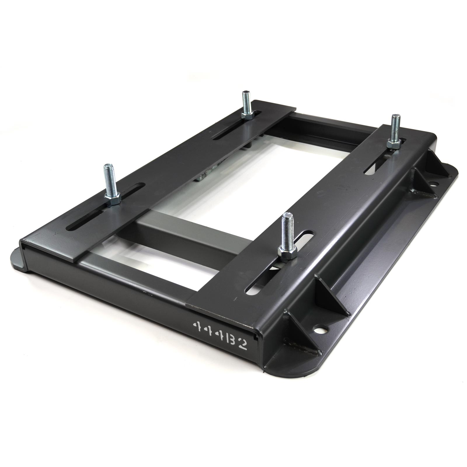
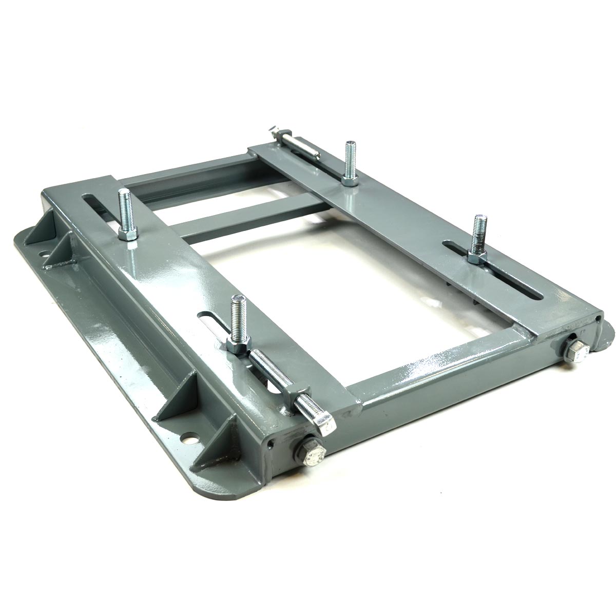
How does a motor base contribute to the stability and alignment of electric motors?
A motor base plays a crucial role in contributing to the stability and alignment of electric motors in industrial applications. Here’s a detailed explanation:
A motor base, also known as a motor mounting base or motor support base, provides essential support and alignment features that help ensure the stable and properly aligned positioning of electric motors. Here’s how a motor base contributes to stability and alignment:
1. Support and Weight Distribution: A motor base serves as a robust platform to support the weight of the electric motor. It helps distribute the motor’s weight evenly across the base, preventing excessive stress or strain on the motor and its mounting points. By providing adequate support, the motor base helps maintain the motor’s structural integrity and prevents any sagging or tilting that could lead to misalignment.
2. Adjustable Mounting Features: Motor bases often include adjustable features such as slotted holes or bolt patterns that allow for precise alignment of the motor. These adjustment options enable technicians to align the motor with connected equipment, such as pumps, fans, conveyors, or gearboxes. Proper alignment is crucial for efficient power transmission, minimizing wear and tear on the motor and connected components, and reducing the risk of mechanical failures.
3. Rigid Construction: Motor bases are typically constructed from sturdy materials like steel or cast iron, which provide rigidity and stability. The robust construction of the motor base helps absorb and dampen vibrations generated during motor operation, minimizing the transmission of vibrations to the surrounding equipment or structure. This vibration control contributes to the overall stability of the motor and its surrounding components.
4. Alignment Verification: Motor bases often include alignment verification features such as laser alignment systems or dial indicators. These tools assist technicians in precisely aligning the motor with connected equipment. By using these verification methods, technicians can ensure that the alignment is within specified tolerances, further enhancing stability and minimizing the risk of misalignment-related issues.
5. Secure Mounting: Motor bases are designed to securely attach the motor to the base, typically using bolts or fasteners. This secure mounting prevents any movement or shifting of the motor during operation, enhancing stability. It also helps maintain the alignment achieved during the installation process.
By providing support, adjustable alignment features, rigidity, alignment verification, and secure mounting, motor bases contribute significantly to the stability and alignment of electric motors in industrial applications. Proper stability and alignment are essential for optimal motor performance, reduced wear and tear, improved energy efficiency, and prolonged motor lifespan.
When installing a motor base, it’s crucial to follow manufacturer guidelines and ensure proper anchoring to the foundation or supporting structure. This helps maintain the integrity of the motor base and ensures the reliable operation of the motor.
In summary, a motor base is a critical component that contributes to the stability and alignment of electric motors by providing support, alignment adjustability, rigidity, alignment verification, and secure mounting, ultimately enhancing motor performance and reliability.
editor by CX 2024-02-02
China Professional DC 3V 5V Mini M10 Gear Motor Precision Planetary Gearbox Gear Reducer Motor DIY Robot Smart Car Toy with Hot selling
Product Description
Warranty:
Other, 3 Months-1 Year
Place of Origin:
ZheJiang , China
Brand Name:
TT motor
Model Number:
TGPP09
Usage:
BOAT, Car, Electric Bicycle, FAN, Home Appliance, Cosmetic instrument, SMART HOME, Smart Robot Car Intelligent Car
Type:
GEAR MOTOR
Torque:
0.15kg.cm
Construction:
Permanent Magnet
Commutation:
Brush
Protect Feature:
Drip-proof
Speed(RPM):
custom
Continuous Current(A):
60mA
Efficiency:
Ie 3
Application:
Home Applicance
Motor type:
PMDC Brushed Motor
Rated Voltage:
3-6V
Keywords:
Low Noise
Gear Material:
Powder Metallurgy
Load Capacity:
1N
Feature:
Long Life Time
Noise:
Low Noise Level
| Application: | Universal, Industrial, Household Appliances, Car, Power Tools, Smart Lock |
|---|---|
| Operating Speed: | Low Speed |
| Excitation Mode: | Compound |
| Function: | Control, Driving |
| Casing Protection: | Protection Type |
| Number of Poles: | 2 |
| Samples: |
US$ 3/Piece
1 Piece(Min.Order) | |
|---|
| Customization: |
Available
| Customized Request |
|---|

The Benefits of Using a Gear Motor
A gear motor works on the principle of conservation of angular momentum. As the smaller gear covers more RPM and the larger gear produces more torque, the ratio between the two is greater than one. Similarly, a multiple gear motor follows the principle of energy conservation, with the direction of rotation always opposite to the one that is adjacent to it. It’s easy to understand the concept behind gear motors and the various types available. Read on to learn about the different types of gears and their applications.
Electric motor
The choice of an electric motor for gear motor is largely dependent on the application. There are various motor and gearhead combinations available, and some are more efficient than others. However, it is critical to understand the application requirements and select a motor that meets these needs. In this article, we’ll examine some of the benefits of using a gear motor. The pros and cons of each type are briefly discussed. You can buy new gear motors at competitive prices, but they aren’t the most reliable or durable option for your application.
To determine which motor is best for your application, you’ll need to consider the load and speed requirements. A gear motor’s efficiency (e) can be calculated by taking the input and output values and calculating their relation. On the graph below, the input (T) and output (P) values are represented as dashed lines. The input (I) value is represented as the torque applied to the motor shaft. The output (P) is the amount of mechanical energy converted. A DC gear motor is 70% efficient at 3.75 lb-in / 2,100 rpm.
In addition to the worm gear motor, you can also choose a compact DC worm gear motor with a variable gear ratio from 7.5 to 80. It has a range of options and can be custom-made for your specific application. The 3-phase AC gear motor, on the other hand, works at a rated power of one hp and torque of 1.143.2 kg-m. The output voltage is typically 220V.
Another important factor is the output shaft orientation. There are two main orientations for gearmotors: in-line and offset. In-line output shafts are most ideal for applications with high torque and short reduction ratios. If you want to avoid backlash, choose a right angle output shaft. An offset shaft can cause the output shaft to become excessively hot. If the output shaft is angled at a certain angle, it may be too large or too small.
Gear reducer
A gear reducer is a special kind of speed reducing motor, usually used in large machinery, such as compressors. These reducers have no cooling fan and are not designed to handle heavy loads. Different purposes require different service factors. For instance, a machine that requires frequent fast accelerations and occasional load spikes needs a gear reducer with a high service factor. A gear reducer that’s designed for long production shifts should be larger than a machine that uses it for short periods of time.
A gear reducer can reduce the speed of a motor by a factor of two. The reduction ratio changes the rotation speed of the receiving member. This change in speed is often required to solve problems of inertia mismatch. The torque density of a gear reducer is measured in newton meters and will depend on the motor used. The first criterion is the configuration of the input and output shafts. A gear ratio of 2:1, for example, means that the output speed has been cut in half.
Bevel gear reducers are a good option if the input and output shafts are perpendicular. This type is very robust and is perfect for situations where the angle between two axes is small. However, bevel gear reducers are expensive and require constant maintenance. They are usually used in heavy-duty conveyors and farm equipment. The correct choice of gear reducer for gear motor is crucial for the efficiency and reliability of the mechanism. To get the best gear reducer for your application, talk to a qualified manufacturer today.
Choosing a gear reducer for a gear motor can be tricky. The wrong one can ruin an entire machine, so it’s important to know the specifics. You must know the torque and speed requirements and choose a motor with the appropriate ratio. A gear reducer should also be compatible with the motor it’s intended for. In some cases, a smaller motor with a gear reducer will work better than a larger one.
Motor shaft
Proper alignment of the motor shaft can greatly improve the performance and life span of rotating devices. The proper alignment of motors and driven instruments enhances the transfer of energy from the motor to the instrument. Incorrect alignment leads to additional noise and vibration. It may also lead to premature failure of couplings and bearings. Misalignment also results in increased shaft and coupling temperatures. Hence, proper alignment is critical to improve the efficiency of the driven instrument.
When choosing the correct type of gear train for your motor, you need to consider its energy efficiency and the torque it can handle. A helical geared motor is more efficient for high output torque applications. Depending on the required speed and torque, you can choose between an in-line and a parallel helical geared motor. Both types of gears have their advantages and disadvantages. Spur gears are widespread. They are toothed and run parallel to the motor shaft.
A planetary gear motor can also have a linear output shaft. A stepping motor should not operate at too high current to prevent demagnetization, which will lead to step loss or torque drop. Ensure that the motor and gearbox output shafts are protected from external impacts. If the motor and gearbox are not protected against bumps, they may cause thread defects. Make sure that the motor shafts and rotors are protected from external impacts.
When choosing a metal for your gear motor’s motor shaft, you should consider the cost of hot-rolled bar stock. Its outer layers are more difficult to machine. This type of material contains residual stresses and other problems that make it difficult to machine. For these applications, you should choose a high-strength steel with hard outer layers. This type of steel is cheaper, but it also has size considerations. It’s best to test each material first to determine which one suits your needs.
In addition to reducing the speed of your device, a geared motor also minimizes the torque generated by your machine. It can be used with both AC and DC power. A high-quality gear motor is vital for stirring mechanisms and conveyor belts. However, you should choose a geared motor that uses high-grade gears and provides maximum efficiency. There are many types of planetary gear motors and gears on the market, and it’s important to choose the right one.
First stage gears
The first stage gears of a gear motor are the most important components of the entire device. The motor’s power transmission is 90% efficient, but there are many factors that can affect its performance. The gear ratios used should be high enough to handle the load, but not too high that they are limiting the motor’s speed. A gear motor should also have a healthy safety factor, and the lubricant must be sufficient to overcome any of these factors.
The transmission torque of the gear changes with its speed. The transmission torque at the input side of the gear decreases, transferring a small torque to the output side. The number of teeth and the pitch circle diameters can be used to calculate the torque. The first stage gears of gear motors can be categorized as spur gears, helical gears, or worm gears. These three types of gears have different torque capacities.
The first stage helical gear is the most important part of a gear motor. Its function is to transfer rotation from one gear to the other. Its output is the gearhead. The second stage gears are connected by a carrier. They work in tandem with the first stage gear to provide the output of the gearhead. Moreover, the first stage carrier rotates in the same direction as the input pinion.
Another important component is the output torque of the gearmotor. When choosing a gearmotor, consider the starting torque, running torque, output speed, overhung and shock loads, duty cycles, and more. It is crucial to choose a gearmotor with the right ratio for the application. By choosing the proper gearmotor, you will get maximum performance with minimal operating costs and increase plant productivity. For more information on first stage gears, check out our blog.
The first stage of a gear motor is composed of a set of fixed and rotating sprockets. The first stage of these gears acts as a drive gear. Its rotational mass is a limiting factor for torque. The second stage consists of a rotating shaft. This shaft rotates in the direction of the torque axis. It is also the limiting force for the motor’s torque.
editor by CX 2023-06-13
China manufacturer 25mm 12V 24V Micro Planetary Gear Motor for Electrical Curtain car motor
Product Description
25mm 12v 24v micro planetary gear motor for electrical curtain
Please kindly let us know
1) what is your requirement to volt?
2) what is your requirement to rpm?
3) what is your requirement toTorque?
4) what is your requirement to Quantity.
Then we will provide solutions accordingly.
Product Category
China manufacturer gear motor price With Professional Technical Support
We always provide customers with distinctive products:cost-effective, lower
noise, higher efficiency and stability, longer life and higher strength.
| Basic information | |||||||||||||||||||||||||||||||||||||||||||||||||||||||||||||||||||||||||||||||||||||||||||||||||||||||||||||||||||||||||||||||||||||||||||||||||||||||||||||||||||||||||||
| Product name | PG25370 series,25mm diameter planet gear motor | ||||||||||||||||||||||||||||||||||||||||||||||||||||||||||||||||||||||||||||||||||||||||||||||||||||||||||||||||||||||||||||||||||||||||||||||||||||||||||||||||||||||||||
| Motor type | carbon-brush commutator | ||||||||||||||||||||||||||||||||||||||||||||||||||||||||||||||||||||||||||||||||||||||||||||||||||||||||||||||||||||||||||||||||||||||||||||||||||||||||||||||||||||||||||
| Gear type | Straight gearwheel,planet construction | ||||||||||||||||||||||||||||||||||||||||||||||||||||||||||||||||||||||||||||||||||||||||||||||||||||||||||||||||||||||||||||||||||||||||||||||||||||||||||||||||||||||||||
| Housing material | Steel | ||||||||||||||||||||||||||||||||||||||||||||||||||||||||||||||||||||||||||||||||||||||||||||||||||||||||||||||||||||||||||||||||||||||||||||||||||||||||||||||||||||||||||
| Geartrain material | Steel and Powdered Metal,POM optional | ||||||||||||||||||||||||||||||||||||||||||||||||||||||||||||||||||||||||||||||||||||||||||||||||||||||||||||||||||||||||||||||||||||||||||||||||||||||||||||||||||||||||||
| Bearing at output shaft | Sleeve bearing | ||||||||||||||||||||||||||||||||||||||||||||||||||||||||||||||||||||||||||||||||||||||||||||||||||||||||||||||||||||||||||||||||||||||||||||||||||||||||||||||||||||||||||
| Lubricant | Grease for high-low temperature, -62—
Contact: Candy Xu Add: NO.1269 Mingshu Road HangZhou Industrial Zone,Xihu (West Lake) Dis. District,HangZhou ZHangZhoug Province China. Post: 315191
The Benefits of Using a Gear MotorA gear motor works on the principle of conservation of angular momentum. As the smaller gear covers more RPM and the larger gear produces more torque, the ratio between the two is greater than one. Similarly, a multiple gear motor follows the principle of energy conservation, with the direction of rotation always opposite to the one that is adjacent to it. It’s easy to understand the concept behind gear motors and the various types available. Read on to learn about the different types of gears and their applications. Electric motorThe choice of an electric motor for gear motor is largely dependent on the application. There are various motor and gearhead combinations available, and some are more efficient than others. However, it is critical to understand the application requirements and select a motor that meets these needs. In this article, we’ll examine some of the benefits of using a gear motor. The pros and cons of each type are briefly discussed. You can buy new gear motors at competitive prices, but they aren’t the most reliable or durable option for your application. Gear reducerA gear reducer is a special kind of speed reducing motor, usually used in large machinery, such as compressors. These reducers have no cooling fan and are not designed to handle heavy loads. Different purposes require different service factors. For instance, a machine that requires frequent fast accelerations and occasional load spikes needs a gear reducer with a high service factor. A gear reducer that’s designed for long production shifts should be larger than a machine that uses it for short periods of time. Motor shaftProper alignment of the motor shaft can greatly improve the performance and life span of rotating devices. The proper alignment of motors and driven instruments enhances the transfer of energy from the motor to the instrument. Incorrect alignment leads to additional noise and vibration. It may also lead to premature failure of couplings and bearings. Misalignment also results in increased shaft and coupling temperatures. Hence, proper alignment is critical to improve the efficiency of the driven instrument. First stage gearsThe first stage gears of a gear motor are the most important components of the entire device. The motor’s power transmission is 90% efficient, but there are many factors that can affect its performance. The gear ratios used should be high enough to handle the load, but not too high that they are limiting the motor’s speed. A gear motor should also have a healthy safety factor, and the lubricant must be sufficient to overcome any of these factors.
China Professional ZD High Torque Low Noise 20 Reduction Ratio Electric Brushless DC Planetary Gear Motor car motorProduct Description
Model Selection ZD Leader has a wide range of micro motor production lines in the industry, including DC Motor, AC Motor, Brushless Motor, Planetary Gear Motor, Drum Motor, Planetary Gearbox, RV Reducer and Harmonic Gearbox etc. Through technical innovation and customization, we help you create outstanding application systems and provide flexible solutions for various industrial automation situations.
• Model Selection • Drawing Request If you need more product parameters, catalogues, CAD or 3D drawings, please contact us. • On Your Need We can modify standard products or customize them to meet your specific needs.
Detailed Photos
Features: Other Related Products Click here to find what you are looking for: Company Profile
FAQ Q: What’re your main products? Q: How to select a suitable motor? Q: Do you have a customized service for your standard motors? Q: Do you have an individual design service for motors? Q: What’s your lead time?
Benefits of a Planetary MotorIf you’re looking for an affordable way to power a machine, consider purchasing a Planetary Motor. These units are designed to provide a massive range of gear reductions, and are capable of generating much higher torques and torque density than other types of drive systems. This article will explain why you should consider purchasing one for your needs. And we’ll also discuss the differences between a planetary and spur gear system, as well as how you can benefit from them. planetary gearsPlanetary gears in a motor are used to reduce the speed of rotation of the armature 8. The reduction ratio is determined by the structure of the planetary gear device. The output shaft 5 rotates through the device with the assistance of the ring gear 4. The ring gear 4 engages with the pinion 3 once the shaft is rotated to the engagement position. The transmission of rotational torque from the ring gear to the armature causes the motor to start. planetary gearboxesA planetary gearbox is a type of drivetrain in which the input and output shafts are connected with a planetary structure. A planetary gearset can have three main components: an input gear, a planetary output gear, and a stationary position. Different gears can be used to change the transmission ratios. The planetary structure arrangement gives the planetary gearset high rigidity and minimizes backlash. This high rigidity is crucial for quick start-stop cycles and rotational direction. planetary gear motorsWhen we think of planetary gear motors, we tend to think of large and powerful machines, but in fact, there are many smaller, more inexpensive versions of the same machine. These motors are often made of plastic, and can be as small as six millimeters in diameter. Unlike their larger counterparts, they have only one gear in the transmission, and are made with a small diameter and small number of teeth. planetary gears vs spur gearsA planetary motor uses multiple teeth to share the load of rotating parts. This gives planetary gears high stiffness and low backlash – often as low as one or two arc minutes. These characteristics are important for applications that undergo frequent start-stop cycles or rotational direction changes. This article discusses the benefits of planetary gears and how they differ from spur gears. You can watch the animation below for a clearer understanding of how they operate and how they differ from spur gears. planetary gearboxes as a compact alternative to pinion-and-gear reducersWhile traditional pinion-and-gear reducer design is bulky and complex, planetary gearboxes are compact and flexible. They are suitable for many applications, especially where space and weight are issues, as well as torque and speed reduction. However, understanding their mechanism and working isn’t as simple as it sounds, so here are some of the key benefits of planetary gearing.
China Sihengmotor factory cnc 5pole motor 60mm 0.64nm AC Servo Motor 200W 220V Motor and Driver for AGV car with high qualityWarranty: 3months-1year two. How can we know the merchandise quality? three. How can we get your catalog? four. Can we have totally free sample? five. Is this your closing value? Could i have the low cost? six.Is there low-cost shipping and delivery expense to import to our country? seven. Can we visit your manufacturing unit? 8.What is the Guarantee for your goods?
Benefits of a Planetary MotorIf you’re looking for an affordable way to power a machine, consider purchasing a Planetary Motor. These units are designed to provide a massive range of gear reductions, and are capable of generating much higher torques and torque density than other types of drive systems. This article will explain why you should consider purchasing one for your needs. And we’ll also discuss the differences between a planetary and spur gear system, as well as how you can benefit from them. planetary gearsPlanetary gears in a motor are used to reduce the speed of rotation of the armature 8. The reduction ratio is determined by the structure of the planetary gear device. The output shaft 5 rotates through the device with the assistance of the ring gear 4. The ring gear 4 engages with the pinion 3 once the shaft is rotated to the engagement position. The transmission of rotational torque from the ring gear to the armature causes the motor to start. planetary gearboxesA planetary gearbox is a type of drivetrain in which the input and output shafts are connected with a planetary structure. A planetary gearset can have three main components: an input gear, a planetary output gear, and a stationary position. Different gears can be used to change the transmission ratios. The planetary structure arrangement gives the planetary gearset high rigidity and minimizes backlash. This high rigidity is crucial for quick start-stop cycles and rotational direction. planetary gear motorsWhen we think of planetary gear motors, we tend to think of large and powerful machines, but in fact, there are many smaller, more inexpensive versions of the same machine. These motors are often made of plastic, and can be as small as six millimeters in diameter. Unlike their larger counterparts, they have only one gear in the transmission, and are made with a small diameter and small number of teeth. planetary gears vs spur gearsA planetary motor uses multiple teeth to share the load of rotating parts. This gives planetary gears high stiffness and low backlash – often as low as one or two arc minutes. These characteristics are important for applications that undergo frequent start-stop cycles or rotational direction changes. This article discusses the benefits of planetary gears and how they differ from spur gears. You can watch the animation below for a clearer understanding of how they operate and how they differ from spur gears. planetary gearboxes as a compact alternative to pinion-and-gear reducersWhile traditional pinion-and-gear reducer design is bulky and complex, planetary gearboxes are compact and flexible. They are suitable for many applications, especially where space and weight are issues, as well as torque and speed reduction. However, understanding their mechanism and working isn’t as simple as it sounds, so here are some of the key benefits of planetary gearing.
China High Quality Wholesale Custom Cheap 3000 RPM 24 Voltage 4 phases Nema 23 Electric Car Kit Brushless Motor motor brushesGuarantee: 3months-1year Why Choose Us Items Description Product Paramenters
The Benefits of Using a Gear MotorA gear motor works on the principle of conservation of angular momentum. As the smaller gear covers more RPM and the larger gear produces more torque, the ratio between the two is greater than one. Similarly, a multiple gear motor follows the principle of energy conservation, with the direction of rotation always opposite to the one that is adjacent to it. It’s easy to understand the concept behind gear motors and the various types available. Read on to learn about the different types of gears and their applications. Electric motorThe choice of an electric motor for gear motor is largely dependent on the application. There are various motor and gearhead combinations available, and some are more efficient than others. However, it is critical to understand the application requirements and select a motor that meets these needs. In this article, we’ll examine some of the benefits of using a gear motor. The pros and cons of each type are briefly discussed. You can buy new gear motors at competitive prices, but they aren’t the most reliable or durable option for your application. Gear reducerA gear reducer is a special kind of speed reducing motor, usually used in large machinery, such as compressors. These reducers have no cooling fan and are not designed to handle heavy loads. Different purposes require different service factors. For instance, a machine that requires frequent fast accelerations and occasional load spikes needs a gear reducer with a high service factor. A gear reducer that’s designed for long production shifts should be larger than a machine that uses it for short periods of time. Motor shaftProper alignment of the motor shaft can greatly improve the performance and life span of rotating devices. The proper alignment of motors and driven instruments enhances the transfer of energy from the motor to the instrument. Incorrect alignment leads to additional noise and vibration. It may also lead to premature failure of couplings and bearings. Misalignment also results in increased shaft and coupling temperatures. Hence, proper alignment is critical to improve the efficiency of the driven instrument. First stage gearsThe first stage gears of a gear motor are the most important components of the entire device. The motor’s power transmission is 90% efficient, but there are many factors that can affect its performance. The gear ratios used should be high enough to handle the load, but not too high that they are limiting the motor’s speed. A gear motor should also have a healthy safety factor, and the lubricant must be sufficient to overcome any of these factors.
China DIY Hand – cranked generator 25MM DC 12V 200RPM Motor 370 dc Gear Box Motor 3V 50RPM 6V 100RPM DC Brush Motor car motorWarranty: 3months-1year Advertising Motor Personalized Specification, Make sure you Contact Us. Reference Drawing ——GM25AM370 “A” Length, You should Check (Gearbox Complex Day). Reference Datasheet
Gearmotor Technical Day
The Basics of a Planetary MotorA Planetary Motor is a type of gearmotor that uses multiple planetary gears to deliver torque. This system minimizes the chances of failure of individual gears and increases output capacity. Compared to the planetary motor, the spur gear motor is less complex and less expensive. However, a spur gear motor is generally more suitable for applications requiring low torque. This is because each gear is responsible for the entire load, limiting its torque. Self-centering planetary gearsThis self-centering mechanism for a planetary motor is based on a helical arrangement. The helical structure involves a sun-planet, with its crown and slope modified. The gears are mounted on a ring and share the load evenly. The helical arrangement can be either self-centering or self-resonant. This method is suited for both applications. High torqueCompared to the conventional planetary motors, high-torque planetary motors have a higher output torque and better transmission efficiency. The high-torque planetary motors are designed to withstand large loads and are used in many types of applications, such as medical equipment and miniature consumer electronics. Their compact design makes them suitable for small space-saving applications. In addition, these motors are designed for high-speed operation. High efficiencyA planetary gearbox is a type of mechanical device that is used for high-torque transmission. This gearbox is made of multiple pairs of gears. Large gears on the output shaft mesh with small gears on the input shaft. The ratio between the big and small gear teeth determines the transmittable torque. High-efficiency planetary gearheads are available for linear motion, axial loads, and sterilizable applications. High costIn general, planetary gearmotors are more expensive than other configurations of gearmotors. This is due to the complexity of their design, which involves the use of a central sun gear and a set of planetary gears which mesh with each other. The entire assembly is enclosed in a larger internal tooth gear. However, planetary motors are more effective for higher load requirements. The cost of planetary motors varies depending on the number of gears and the number of planetary gears in the system.
China 3000w 4kw 4000w 5kw 7kw Electric BLDC Brushless DC Motor 48v 1hp 1kw 2kw 3kw Car Custom Duty Copper Customized Frame Controller wholesalerWarranty: 3 months Goods Description Advise Merchandise Why Decide on Us Business Profile Item packaging Q:What is the Minimum quantity?A:MOQ is 1 pcs for any items Q:What’ 3-6V Little dc Motor type a hundred thirty toy vehicle motor with cable DC pastime motor for pastime intelligent auto stem s your hottest sale items?A:A11VLO collection piston pump and A6VM piston motor , they are extensively used in crane , drilling rig ,excavator,maritime . Q:Do you assistance to personalize?A:Sure, relies upon on Amount. Q:Do you support to source sample just before official buy?A:Of course , 120rpm 2kg.cm one hundred fifty ratio price substantial torque 12v dc planetary geared motor for RC automobile bigfoot boat model of course we do Q:How prolonged can you ship the products?A:Relies upon on Product and amount, we have stock for some common designs Q:Do you assist to personalize the Brand and package deal?A:Sure,relies upon on the amount Q:Which transportation modes do you support? A:By sea , By air , By prepare ,By truck, Inch Stainless Metal Double Split Shaft Clamp Collar for restricted shaft shaft locking collars By express ,it is up to buyer. Q:What’s the manner of payment you assist?A:TT,PAYPAL,WESTERN UNION,L/C Q:What’ 1-12 Bore One Break up Shaft Collar Black Oxide Established Screw s the warranty of your goods?A:One particular year right after leaving our manufacturing unit
The Basics of a Planetary MotorA Planetary Motor is a type of gearmotor that uses multiple planetary gears to deliver torque. This system minimizes the chances of failure of individual gears and increases output capacity. Compared to the planetary motor, the spur gear motor is less complex and less expensive. However, a spur gear motor is generally more suitable for applications requiring low torque. This is because each gear is responsible for the entire load, limiting its torque. Self-centering planetary gearsThis self-centering mechanism for a planetary motor is based on a helical arrangement. The helical structure involves a sun-planet, with its crown and slope modified. The gears are mounted on a ring and share the load evenly. The helical arrangement can be either self-centering or self-resonant. This method is suited for both applications. High torqueCompared to the conventional planetary motors, high-torque planetary motors have a higher output torque and better transmission efficiency. The high-torque planetary motors are designed to withstand large loads and are used in many types of applications, such as medical equipment and miniature consumer electronics. Their compact design makes them suitable for small space-saving applications. In addition, these motors are designed for high-speed operation. High efficiencyA planetary gearbox is a type of mechanical device that is used for high-torque transmission. This gearbox is made of multiple pairs of gears. Large gears on the output shaft mesh with small gears on the input shaft. The ratio between the big and small gear teeth determines the transmittable torque. High-efficiency planetary gearheads are available for linear motion, axial loads, and sterilizable applications. High costIn general, planetary gearmotors are more expensive than other configurations of gearmotors. This is due to the complexity of their design, which involves the use of a central sun gear and a set of planetary gears which mesh with each other. The entire assembly is enclosed in a larger internal tooth gear. However, planetary motors are more effective for higher load requirements. The cost of planetary motors varies depending on the number of gears and the number of planetary gears in the system.
China Double Chin Reducer Machine Miner Noise Planetary Gear Car Mileage Elbow Tee Reducer Pipe Fitting Three-Phase Asynchronous Motor Type Rat Bushing Monomer Odor dc motorProduct Description
double chin reducer device miner sounds planetary equipment automobile HangZhouage elbow tee reducer pipe fitting 3-period asynchronous motor variety rat bushing monomer odor
###
###
###
###
The Benefits of Using a Gear MotorA gear motor works on the principle of conservation of angular momentum. As the smaller gear covers more RPM and the larger gear produces more torque, the ratio between the two is greater than one. Similarly, a multiple gear motor follows the principle of energy conservation, with the direction of rotation always opposite to the one that is adjacent to it. It’s easy to understand the concept behind gear motors and the various types available. Read on to learn about the different types of gears and their applications. Electric motorThe choice of an electric motor for gear motor is largely dependent on the application. There are various motor and gearhead combinations available, and some are more efficient than others. However, it is critical to understand the application requirements and select a motor that meets these needs. In this article, we’ll examine some of the benefits of using a gear motor. The pros and cons of each type are briefly discussed. You can buy new gear motors at competitive prices, but they aren’t the most reliable or durable option for your application. Gear reducerA gear reducer is a special kind of speed reducing motor, usually used in large machinery, such as compressors. These reducers have no cooling fan and are not designed to handle heavy loads. Different purposes require different service factors. For instance, a machine that requires frequent fast accelerations and occasional load spikes needs a gear reducer with a high service factor. A gear reducer that’s designed for long production shifts should be larger than a machine that uses it for short periods of time. Motor shaftProper alignment of the motor shaft can greatly improve the performance and life span of rotating devices. The proper alignment of motors and driven instruments enhances the transfer of energy from the motor to the instrument. Incorrect alignment leads to additional noise and vibration. It may also lead to premature failure of couplings and bearings. Misalignment also results in increased shaft and coupling temperatures. Hence, proper alignment is critical to improve the efficiency of the driven instrument. First stage gearsThe first stage gears of a gear motor are the most important components of the entire device. The motor’s power transmission is 90% efficient, but there are many factors that can affect its performance. The gear ratios used should be high enough to handle the load, but not too high that they are limiting the motor’s speed. A gear motor should also have a healthy safety factor, and the lubricant must be sufficient to overcome any of these factors.
| ||||||||||||||||||||||||||||||||||||||||||||||||||||||||||||||||||||||||||||||||||||||||||||||||||||||||||||||||||||||||||||||||||||||||||||||||||||||||||||||||||||||||||


