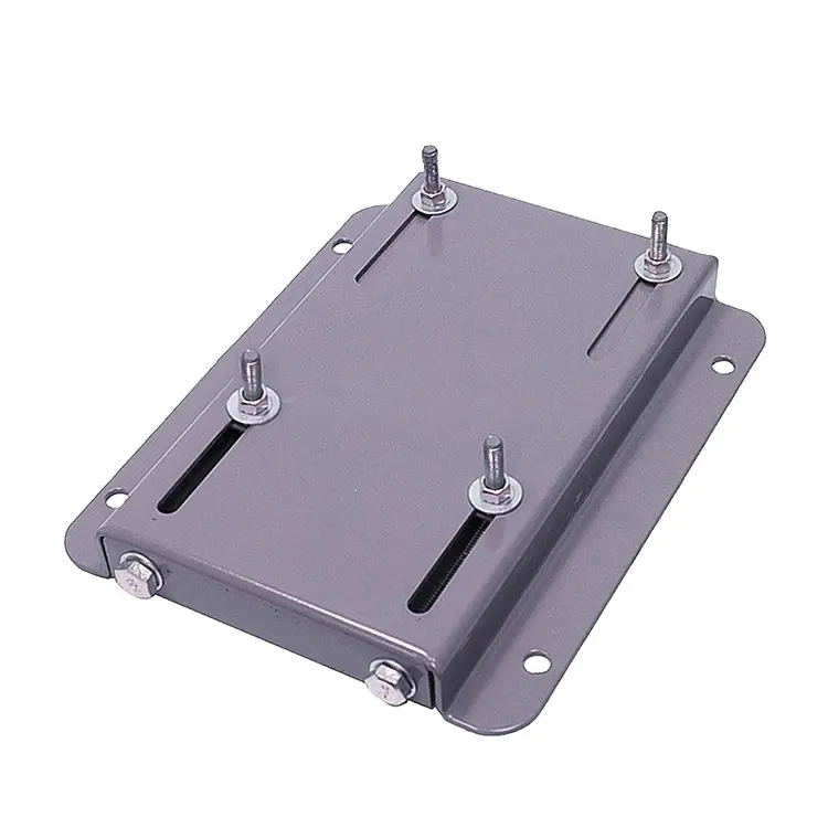
Product Description
Product Description
| Material: | ADC-12 |
| Cavity Number: | 1 |
| Process Technology: | High pressure die casting |
| Product Dimensions: | Customized |
| Casting General Tolerance: | Grade GB-CT4 |
| Surface Finish: | Polishing, Vibratory deburring,Anodizing, Power Coating, Painting,etc |
| Flow Processes: | Die casting, Trimming, Polishing, vibratory deburring, Machining, Cleaning,Packing, Shipping |
| Control Measure: | Incoming Material Test, First Article inspection, Routing inspection, Final item inspection, and Outgoing quality control |
| Inspection Equipment: | CMM, Caliper, Plug Gage,Thread Gage,Tensile Tester,Roughness Meter,Spectrograph,Air Gage,Air Leak Test,Projector,Pneumatic Measuring Tool,etc. |
| Application: | Auto Parts |
| Certificate: | IATF16949:2016 |
| Lead Time | 30-35 days |
| Trade Term: | FOB HangZhou |
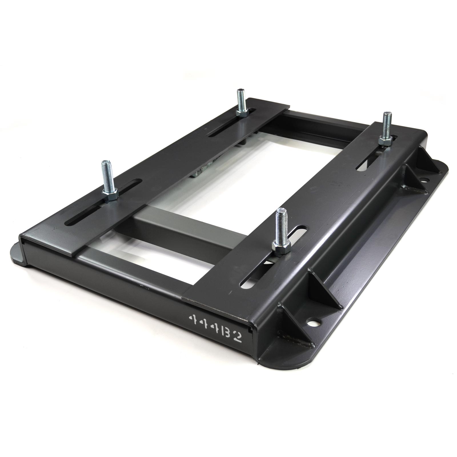
Detailed Photos
Certifications
Company Profile
BOLANG, established in 2001, specializes in manufacturing aluminum & zinc alloy die castings, serving automotive components, agricultural machinery parts, construction components, lighting accessories, and various precision machined parts industries.
The company possesses a highly qualified staff team. Technical engineers are with decades’ experience in die-casting techniques such as vacuum casting and squeezing pin technology.
In order to establish a steady production system, the company possesses die-casting equipment ranging from 280 tons to 1200 tons.
To meet the quality control standards, the company is equipped with CMM, spectrometer, image measuring instrument, blue light scanner, magnifier, digital layer thickness gauge, leak tester, hardness tester, roughness tester, and electron microscope.
The company also awarded certificate as IATF16949, ISO14001, ISO45001, etc.
About Malaysia Branch Factory
In order for US clients to reduce 25%-35% import tariff and save the cost, we set up a Malaysia branch factory – RONGKUN METAL PRODUCTS SDN BHD. We plan to equip 3 die casting machines (280T, 400T, 630T) and 5 CNC, CMM and other measurement equipment as well.
We will manage to get the certificate of IATF16949, ISO14001 for this branch factory in 2571.
FAQ
| FAQ |
| Q1. When can I get the price? |
| A: We usually quote within 2-3 days after we receive the RFQ or feedback within 2 days if any questions on prints need to be confirmed. |
| Q2. How long is the lead-time for mold? |
| A: Usually it depends on the size and complexity of the mold. But normally, the lead time is 35-45days. |
| Q3. I have no 3D drawing, how should I start the new project? |
| A: You can supply us a sample, we will help work on establishing 3D model accordingly. |
| Q4. Before shipment, how to ensure the products quality? |
| A: We have strict development procedure, during samples development, we have capacity to produce according to PPA, after PSW approved. |
| Condition: | New |
|---|---|
| Certification: | IATF16949:2016 |
| Standard: | DIN, ASTM, GOST, GB, JIS, ANSI, BS |
| Customized: | Customized |
| Material: | Aluminum, Aluminium, Zinc, Zamak |
| Application: | Metal Processing Machinery Parts, Metal Casting Machinery |
| Customization: |
Available
|
|
|---|
Can motor bases accommodate motors with varying horsepower ratings?
Motor bases are designed to accommodate motors with varying horsepower ratings. Here’s a detailed explanation:
Motor bases are versatile mounting platforms that can accommodate a wide range of motors, including those with different horsepower ratings. The horsepower rating of a motor refers to its power output capability and is an important consideration when selecting a motor for a specific application.
Motor bases are typically designed to support a range of motor sizes and power ratings. They are manufactured with load-bearing capacities that can handle motors with varying horsepower requirements. The specific horsepower ratings that a motor base can accommodate will depend on its design, construction, and intended application.
When selecting a motor base, it’s important to consider the horsepower rating of the motor you intend to mount. Ensure that the motor base’s load-bearing capacity is sufficient to support the weight and dynamic forces generated by the motor during operation. Exceeding the load-bearing capacity of the motor base can lead to instability, increased vibrations, and potential safety hazards.
Motor bases are often labeled or specified with their load ratings, which indicate the maximum weight or horsepower they can support. It’s crucial to verify that the motor base’s load rating aligns with or exceeds the horsepower rating of the motor you plan to install.
Additionally, consider other factors such as the specific application requirements, environmental conditions, installation constraints, and any industry or safety standards. These considerations will help ensure that the motor base is suitable for the motor’s horsepower rating and the demands of the application.
It’s worth noting that while motor bases can accommodate motors with varying horsepower ratings, it’s essential to follow the manufacturer’s recommendations and guidelines for proper motor base selection, installation, and usage. Adhering to these guidelines ensures the motor base’s structural integrity, stability, and overall performance.
In summary, motor bases are designed to accommodate motors with varying horsepower ratings. They are manufactured with load-bearing capacities that can support a range of motor sizes and power requirements. When selecting a motor base, verify that its load rating aligns with or exceeds the horsepower rating of the motor being installed. By considering the specific requirements of the motor and the application, you can ensure a well-matched motor base that provides optimal support, stability, and performance.
Can motor bases be used in outdoor or harsh environmental conditions?
Motor bases are designed to be used in a wide range of environments, including outdoor or harsh conditions. Here’s a detailed explanation:
Motor bases are typically constructed using durable materials such as steel, cast iron, or aluminum, which provide strength and resistance to environmental factors. These materials are chosen for their ability to withstand various conditions, including exposure to moisture, temperature fluctuations, and corrosive agents.
1. Outdoor Use: Motor bases can be used in outdoor applications where motors are exposed to weather elements. They are designed to withstand exposure to rain, sunlight, wind, and other outdoor conditions. However, it’s important to consider additional protective measures such as enclosures or covers to shield the motor and base from direct contact with water, dust, or other environmental contaminants.
2. Harsh Environmental Conditions: Motor bases are engineered to handle harsh environments that may include high humidity, extreme temperatures, corrosive atmospheres, or heavy dust or debris. Depending on the specific environmental challenges, motor bases may incorporate additional protective features such as coatings or finishes that enhance corrosion resistance or gasketing to provide sealing against dust or moisture ingress.
3. Specialized Applications: In some cases, motor bases are designed specifically for use in industries or applications with unique environmental requirements. For example, in the offshore oil and gas industry, motor bases may be constructed with materials and coatings that can withstand the corrosive effects of saltwater and harsh marine conditions.
4. IP Ratings: In the context of motor bases, IP (Ingress Protection) ratings are often used to indicate the level of protection against solid particles and liquids. Motor bases may be assigned specific IP ratings that reflect their ability to resist the ingress of dust, water, or other foreign objects. Higher IP ratings indicate greater protection. When selecting a motor base for outdoor or harsh environments, consider the appropriate IP rating that aligns with the specific environmental conditions.
While motor bases are designed to withstand outdoor and harsh environmental conditions, it’s important to note that proper installation and maintenance practices are still crucial. Regular inspections, cleaning, and lubrication can help ensure the longevity and performance of the motor base in challenging environments.
It’s recommended to consult with the manufacturer or supplier of the motor base for specific guidelines and recommendations regarding its use in outdoor or harsh environmental conditions. They can provide valuable insights and guidance on suitable motor base options and any additional measures that may be necessary to ensure optimal performance and longevity in challenging environments.
What materials are commonly used in the construction of durable motor bases?
Durable motor bases are constructed using various materials that provide strength, stability, and longevity. Here’s a detailed explanation:
Motor bases are designed to withstand the weight and operational forces of electric motors while maintaining stability and alignment. The choice of materials for motor base construction depends on factors such as the motor size, application requirements, and environmental conditions. Here are some commonly used materials:
1. Steel: Steel is one of the most commonly used materials for motor bases due to its exceptional strength and durability. Motor bases made of steel can withstand heavy loads and resist deformation. Steel motor bases are known for their rigidity, stability, and ability to dampen vibrations. They are suitable for a wide range of motor sizes and industrial applications.
2. Cast Iron: Cast iron is another popular material for motor bases, especially for larger motor sizes. Cast iron offers excellent stability and resistance to deformation under heavy loads. It has high compressive strength and can effectively absorb and dampen vibrations generated during motor operation. Cast iron motor bases are known for their long-lasting performance and suitability for demanding industrial environments.
3. Aluminum: Aluminum motor bases are commonly used for smaller or lighter motor applications. Aluminum is lightweight, corrosion-resistant, and offers good thermal conductivity. Motor bases made of aluminum are easy to handle and install. They are often preferred in applications where weight reduction is desired, such as in portable or mobile equipment.
4. Composite Materials: In some cases, motor bases may be constructed using composite materials such as fiberglass-reinforced plastic (FRP). Composite motor bases offer a combination of strength, lightweight construction, and corrosion resistance. They are particularly suitable for applications where weight reduction, electrical insulation, or resistance to chemicals and corrosive environments are important considerations.
5. Other Materials: Depending on specific requirements, motor bases can also be constructed using other materials such as stainless steel, galvanized steel, or specialized alloys. These materials may be chosen for their specific properties, such as resistance to corrosion, high-temperature applications, or compatibility with certain environmental conditions.
When selecting a motor base material, it’s essential to consider factors such as load capacity, environmental conditions (such as exposure to moisture, chemicals, or extreme temperatures), and the specific needs of the application.
In summary, durable motor bases are commonly constructed using materials such as steel, cast iron, aluminum, composite materials, and other specialized alloys. Each material offers specific advantages in terms of strength, stability, weight, corrosion resistance, and other properties, allowing motor bases to withstand the demands of industrial applications.


editor by CX 2023-11-27
China Custom 22mm 12V 24V DC Planetary Geared Motor for Automatic Actuator wholesaler
Product Description
22mm 12V 24V DC Planet Geared Motor for Automatic actuator
1.Technical specifications:
1. Planet gear motor size: From dia. 22mm to dia. 83mm
2. Fit for small size big output power equipment.
3. The specifications can be designed according to the customer’s requirements!
4. The motor have low noise,long life,high torque.
5. The motor can add encoder
6.Typical applications: Laminator, Paper Shredder, Rotating Christmas Tree Stand, fan, electric oven, grill.
We also can adjust dc motor specifications and output shaft size according to your special requirement.
Welcome to buy DC motor!
2.Production Flow
3.Company Information
In recent 10 years, DERRY has been dedicated to the manufacture of the motor products and the main products can be classified into the following series, namely DC motor, DC gear motor, AC motor, AC gear motor, Stepper motor, Stepper gear motor, Servo motor and Linear actuator series.
Our motor products are widely applied in the fields of aerospace industry, automotive industry, financial equipment, household appliance, industrial automation and robotics, medical equipment, office equipment, packing machinery and transmission industry, offering customers reliable tailored solutions for driving and controlling.
4.Our Services
1). General Service:
|
Quick Reply |
All enquiry or email be replied in 12 hours, no delay for your business. |
|
Professional Team |
Questions about products will be replied professionally, exactly, best advice to you. |
|
Short Lead time |
Sample or small order sent in 7-15 days, bulk or customized order about 30 days. |
|
Payment Choice |
T/T, Western Union,, L/C, etc, easy for your business. |
|
Before shipment |
Take photos, send to customers for confirmation. Only confirmed, can be shipped out. |
|
Language Choice |
Besides English, you can use your own language by email, then we can translate it. |
2). Customization Service:
Motor specification(no-load speed , voltage, torque , diameter, noise, life, testing) and shaft length can be tailor-made according to customer’s requirements.
5.Package & Shipping
| Application: | Universal, Industrial, Household Appliances, Car, Power Tools |
|---|---|
| Operating Speed: | Low Speed |
| Excitation Mode: | Excited |
| Function: | Driving |
| Casing Protection: | Closed Type |
| Number of Poles: | 2 |
| Samples: |
US$ 20/Piece
1 Piece(Min.Order) | |
|---|
| Customization: |
Available
| Customized Request |
|---|

Benefits of a Planetary Motor
A planetary motor has many benefits. Its compact design and low noise makes it a good choice for any application. Among its many uses, planetary gear motors are found in smart cars, consumer electronics, intelligent robots, communication equipment, and medical technology. They can even be found in smart homes! Read on to discover the benefits of a planetary gear motor. You’ll be amazed at how versatile and useful it is!
Self-centering planet gears ensure a symmetrical force distribution
A planetary motor is a machine with multiple, interlocking planetary gears. The output torque is inversely proportional to the diameters of the planets, and the transmission size has no bearing on the output torque. A torsional stress analysis of the retaining structure for this type of motor found a maximum shear stress of 64 MPa, which is equivalent to a safety factor of 3.1 for 6061 aluminum. Self-centering planet gears are designed to ensure a symmetrical force distribution throughout the transmission system, with the weakest component being the pinions.
A planetary gearbox consists of ring and sun gears. The pitch diameters of ring and planet gears are nearly equal. The number of teeth on these gears determines the average gear-ratio per output revolution. This error is related to the manufacturing precision of the gears. The effect of this error is a noise or vibration characteristic of the planetary gearbox.
Another design for a planetary gearbox is a traction-based variant. This design eliminates the need for timing marks and other restrictive assembly conditions. The design of the ring gear is similar to that of a pencil sharpener mechanism. The ring gear is stationary while planet gears extend into cylindrical cutters. When placed on the sun’s axis, the pencil sharpening mechanism revolves around the ring gear to sharpen the pencil.
The JDS eliminates the need for conventional planetary carriers and is mated with the self-centering planet gears by dual-function components. The dual-function components synchronize the rolling motion and traction of the gears. They also eliminate the need for a carrier and reduce the force distribution between the rotor and stator.
Metal gears
A planetary motor is a type of electric drive that uses a series of metal gears. These gears share a load attached to the output shaft to generate torque. The planetary motor is often CNC controlled, with extra-long shafts, which allow it to fit into very compact designs. These gears are available in sizes from seven millimeters to 12 millimeters. They can also be fitted with encoders.
Planetary gearing is widely used in various industrial applications, including automobile transmissions, off-road transmissions, and wheel drive motors. They are also used in bicycles to power the shift mechanism. Another use for planetary gearing is as a powertrain between an internal combustion engine and an electric motor. They are also used in forestry applications, such as debarking equipment and sawing. They can be used in other industries as well, such as pulp washers and asphalt mixers.
Planetary gear sets are composed of three types of gears: a sun gear, planet gears, and an outer ring. The sun gear transfers torque to the planet gears, and the planet gears mesh with the outer ring gear. Planet carriers are designed to deliver high-torque output at low speeds. These gears are mounted on carriers that are moved around the ring gear. The planet gears mesh with the ring gears, and the sun gear is mounted on a moveable carrier.
Plastic planetary gear motors are less expensive to produce than their metal counterparts. However, plastic gears suffer from reduced strength, rigidity, and load capacity. Metal gears are generally easier to manufacture and have less backlash. Plastic planetary gear motor bodies are also lighter and less noisy. Some of the largest plastic planetary gear motors are made in collaboration with leading suppliers. When buying a plastic planetary gear motor, be sure to consider what materials it is made of.
Encoder
The Mega Torque Planetary Encoder DC Geared Motor is designed with a Japanese Mabuchi motor RS-775WC, a 200 RPM base motor. It is capable of achieving stall torque at low speeds, which is impossible to achieve with a simple DC motor. The planetary encoder provides five pulses per revolution, making it perfect for applications requiring precise torque or position. This motor requires an 8mm hex coupling for proper use.
This encoder has a high resolution and is suitable for ZGX38REE, ZGX45RGG and ZGX50RHH. It features a magnetic disc and poles and an optical disc to feed back signals. It can count paulses as the motor passes through a hall on the circuit board. Depending on the gearbox ratio, the encoder can provide up to two million transitions per rotation.
The planetary gear motor uses a planetary gear system to distribute torque in synchrony. This minimizes the risk of gear failure and increases the overall output capacity of the device. On the other hand, a spur gear motor is a simpler design and cheaper to produce. The spur gear motor works better for lower torque applications as each gear bears all the load. As such, the torque capacity of the spur gear motor is lower than that of a planetary gear motor.
The REV UltraPlanetary gearbox is designed for FTC and has three different output shaft options. The output shaft is made of 3/8-inch hex, allowing for flexible shaft replacement. These motors are a great value as they can be used to meet a wide range of power requirements. The REV UltraPlanetary gearbox and motor are available for very reasonable prices and a female 5mm hex output shaft can be used.
Durability
One of the most common questions when selecting a planetary motor is “How durable is it?” This is a question that’s often asked by people. The good news is that planetary motors are extremely durable and can last for a long time if properly maintained. For more information, read on! This article will cover the durability and efficiency of planetary gearmotors and how you can choose the best one for your needs.
First and foremost, planetary gear sets are made from metal materials. This increases their lifespan. The planetary gear set is typically made of metals such as nickel-steel and steel. Some planetary gear motors use plastic. Steel-cut gears are the most durable and suitable for applications that require more torque. Nickel-steel gears are less durable, but are better able to hold lubricant.
Durability of planetary motor gearbox is important for applications requiring high torque versus speed. VEX VersaPlanetary gearboxes are designed for FRC(r) use and are incredibly durable. They are expensive, but they are highly customizable. The planetary gearbox can be removed for maintenance and replacement if necessary. Parts for the gearbox can be purchased separately. VEX VersaPlanetary gearboxes also feature a pinion clamped onto the motor shaft.
Dynamic modeling of the planetary gear transmission system is important for understanding its durability. In previous studies, uncoupled and coupled meshing models were used to investigate the effect of various design parameters on the vibration characteristics of the planetary gear system. This analysis requires considering the role of the mesh stiffness, structure stiffness, and moment of inertia. Moreover, dynamic models for planetary gear transmission require modeling the influence of multiple parameters, such as mesh stiffness and shaft location.
Cost
The planetary gear motor has multiple contact points that help the rotor rotate at different speeds and torques. This design is often used in stirrers and large vats of liquid. This type of motor has a low initial cost and is more commonly found in low-torque applications. A planetary gear motor has multiple contact points and is more effective for applications requiring high torque. Gear motors are often found in stirring mechanisms and conveyor belts.
A planetary gearmotor is typically made from four mechanically linked rotors. They can be used for various applications, including automotive and laboratory automation. The plastic input stage gears reduce noise at higher speeds. Steel gears can be used for high torques and a modified lubricant is often added to reduce weight and mass moment of inertia. Its low-cost design makes it an excellent choice for robots and other applications.
There are many different types of planetary gear motors available. A planetary gear motor has three gears, the sun gear and planet gears, with each sharing equal amounts of work. They are ideal for applications requiring high torque and low-resistance operation, but they require more parts than their single-stage counterparts. The steel cut gears are the most durable, and are often used in applications that require high speeds. The nickel-steel gears are more absorptive, which makes them better for holding lubricant.
A planetary gear motor is a high-performance electrical vehicle motor. A typical planetary gear motor has a 3000 rpm speed, a peak torque of 0.32 Nm, and is available in 24V, 36V, and 48V power supply. It is also quiet and efficient, requiring little maintenance and offering greater torque to a modern electric car. If you are thinking of buying a planetary gear motor, be sure to do a bit of research before purchasing one.
editor by CX 2023-06-12
China Custom NEMA 8 Hybrid Planetary Gearhead Reduced Stepper Gear Motor 1.8deg wholesaler
Product Description
NEMA 8 Hybrid Planetary Gearhead Reduced Stepper Gear Motor 1.8Deg
• Manufacturer Part Number: HP201
• Motor Type: Planetary Gearbox Stepper Motor Bipolar 4 Wires 2 Phase
• Frame Size: 20x20mm Geared Stepper Motor Nema 8 Mounting
• Step Angle: 1.8deg
• Gearbox Effiency: 66%—90%
• Application: 3D Printer motor
HP201-1 20MM
Stepper Angel: 1.8
Drawing of NEMA 8 Hybrid Stepper Gear Motor:
| Motor Electrical Specification | |||||||||
| Series Model | Step Angle ( o ) | L (mm) |
Rated Current (A) | Phase Resistance (Ω) |
Phase Inductance (mH) |
Holding Torque (N.cm) |
Detent Torque (N.cm) | Lead Wire (NO.) |
Motor Weight ( g) |
| HP201-57121 | 1.8 | 28 | 0.2 | 23 | 8.2 | 1.4 | 0.2 | 4 | 50 |
| HP201-57121 | 1.8 | 34 | 0.2 | 25 | 8.4 | 1.8 | 0.3 | 4 | 70 |
| HP201-0 0571 1 | 1.8 | 40 | 0.2 | 32 | 8.8 | 2.6 | 0.5 | 4 | 82 |
| Other Motor Electrical Specification please refer to Hybrid Stepper Motor web | |||||||||
| Gearbox Specification | ||||||||||||
| Ratio | 3.71 | 5.18 | 14 | 19 | 27 | 51 | 71 | 100 | 139 | 189 | 264 | 369 |
| Reducer Series | 1 | 2 | 3 | 4 | ||||||||
| Length ( mm) |
22.4 | 33.0 | 41.5 | 49.8 | ||||||||
| Allowable Torque (Kg.cm) |
6 | 10 | 16 | 20 | ||||||||
| Instantaneous Torque (Kg.cm) |
18 | 30 | 48 | 60 | ||||||||
| Efficiency (%) |
90% | 81% | 73% | 66% | ||||||||
| Weight (g) |
35 | 45 | 55 | 65 | ||||||||
| We can manufacture products according to customer’s requirements | ||||||||||||
Factory Ability:
I.CH Motion Co., Ltd., established in 2006, and our main products are hybrid stepper motor, stepping motor driver, step engine, stepping engine, integrated step servo motors, integrated step AC servo motors, Brushless DC Motors, Brushless Servo Motors and so on. Our products are widely used and applied in the following industries: lighting system, projector, CNC, semiconductor, textile, laser, woodworking, printing, advertising, clothing, marble and ceramic, robotics and military.
Advantages:
1. Short Lead-Time;
2. 0.1% defect rate and;
3. 1 – 2 year guarantee period;
Package:
-Pack by PE foam in cartons, crates, and pallets;
-Shipping via sea, air, courier;
-Lead-time: 3-8 weeks.
We can also supply below products,
FAQ:
Q1. What phase is this stepping motor?
A: It is 2 phases with 1.8deg.
Q2. What is frame size for NEMA 8 Step Geared motor?
A: It is a 20mm*20mm size.
Q3. I need a non-standard motor for my application, can you help?
A: Certainly, most of our customers request custom configurations in 1 form or another. If you plan on replacing a motor in an existing application, just send us a drawing or sample and we can help you find a suitable replacement. Alternatively, contact us and describe your application, our engineers will work with you to create a solution tailor-made for you.
Q4: How can I get your quotation of an electrical step engine?
A: Please send us the details of the stepper motors you arneedalso inincludehe quantity.
Q. What are your Stepper Motors can be used to?
A: Our step motors can be used in CNC routers, CNC milling machine, engraving machine, packaging machine, filling machine, cutting machine, printing machine, laser machine, carving machine, labeling machine, CCTV and robot.
Q. What kind of payment methods do you accept?
A: We can accept Paypal including, TT.
Q: What kind of shipping methods do you use?
A:1) For samples or small batch of the micro stepper motor, air shipping is recommended. (DHL, FedEx, TNT, UPS, EMS), We will provide the tracking No. Once we get it after we ship out the products.
2)For mass production or a big batch of stepping motors, CZPT shipping/sea shipment is recommended.
Q: What is the lead time of stepper motors?
A: For mass production, the lead time depends on the quantities you need.
Q: What is your warranty time?
A: Warranty time: 12 months. And we provide life-long technical service and after-sale service.
Q: Can you make customized shafts?
A: We can make a single shaft, double shaft or other shapes.
Q: What is the NEMA size of this motor?
A: It is NEMA 8 with 1.8 degrees or 0.9 degrees.
Q: What is the application for NEMA 8 StepperGeared Motor
A: It could used as 3D Printer motor.
| Speed: | Low Speed |
|---|---|
| Number of Stator: | Two-Phase |
| Excitation Mode: | HB-Hybrid |
| Function: | Control |
| Number of Poles: | 2 |
| Operate Mode: | Hb Stepper Motor |
| Customization: |
Available
| Customized Request |
|---|
Benefits of a Planetary Motor
A planetary motor has many benefits. Its compact design and low noise makes it a good choice for any application. Among its many uses, planetary gear motors are found in smart cars, consumer electronics, intelligent robots, communication equipment, and medical technology. They can even be found in smart homes! Read on to discover the benefits of a planetary gear motor. You’ll be amazed at how versatile and useful it is!
Self-centering planet gears ensure a symmetrical force distribution
A planetary motor is a machine with multiple, interlocking planetary gears. The output torque is inversely proportional to the diameters of the planets, and the transmission size has no bearing on the output torque. A torsional stress analysis of the retaining structure for this type of motor found a maximum shear stress of 64 MPa, which is equivalent to a safety factor of 3.1 for 6061 aluminum. Self-centering planet gears are designed to ensure a symmetrical force distribution throughout the transmission system, with the weakest component being the pinions.
A planetary gearbox consists of ring and sun gears. The pitch diameters of ring and planet gears are nearly equal. The number of teeth on these gears determines the average gear-ratio per output revolution. This error is related to the manufacturing precision of the gears. The effect of this error is a noise or vibration characteristic of the planetary gearbox.
Another design for a planetary gearbox is a traction-based variant. This design eliminates the need for timing marks and other restrictive assembly conditions. The design of the ring gear is similar to that of a pencil sharpener mechanism. The ring gear is stationary while planet gears extend into cylindrical cutters. When placed on the sun’s axis, the pencil sharpening mechanism revolves around the ring gear to sharpen the pencil.
The JDS eliminates the need for conventional planetary carriers and is mated with the self-centering planet gears by dual-function components. The dual-function components synchronize the rolling motion and traction of the gears. They also eliminate the need for a carrier and reduce the force distribution between the rotor and stator.
Metal gears
A planetary motor is a type of electric drive that uses a series of metal gears. These gears share a load attached to the output shaft to generate torque. The planetary motor is often CNC controlled, with extra-long shafts, which allow it to fit into very compact designs. These gears are available in sizes from seven millimeters to 12 millimeters. They can also be fitted with encoders.
Planetary gearing is widely used in various industrial applications, including automobile transmissions, off-road transmissions, and wheel drive motors. They are also used in bicycles to power the shift mechanism. Another use for planetary gearing is as a powertrain between an internal combustion engine and an electric motor. They are also used in forestry applications, such as debarking equipment and sawing. They can be used in other industries as well, such as pulp washers and asphalt mixers.
Planetary gear sets are composed of three types of gears: a sun gear, planet gears, and an outer ring. The sun gear transfers torque to the planet gears, and the planet gears mesh with the outer ring gear. Planet carriers are designed to deliver high-torque output at low speeds. These gears are mounted on carriers that are moved around the ring gear. The planet gears mesh with the ring gears, and the sun gear is mounted on a moveable carrier.
Plastic planetary gear motors are less expensive to produce than their metal counterparts. However, plastic gears suffer from reduced strength, rigidity, and load capacity. Metal gears are generally easier to manufacture and have less backlash. Plastic planetary gear motor bodies are also lighter and less noisy. Some of the largest plastic planetary gear motors are made in collaboration with leading suppliers. When buying a plastic planetary gear motor, be sure to consider what materials it is made of.
Encoder
The Mega Torque Planetary Encoder DC Geared Motor is designed with a Japanese Mabuchi motor RS-775WC, a 200 RPM base motor. It is capable of achieving stall torque at low speeds, which is impossible to achieve with a simple DC motor. The planetary encoder provides five pulses per revolution, making it perfect for applications requiring precise torque or position. This motor requires an 8mm hex coupling for proper use.
This encoder has a high resolution and is suitable for ZGX38REE, ZGX45RGG and ZGX50RHH. It features a magnetic disc and poles and an optical disc to feed back signals. It can count paulses as the motor passes through a hall on the circuit board. Depending on the gearbox ratio, the encoder can provide up to two million transitions per rotation.
The planetary gear motor uses a planetary gear system to distribute torque in synchrony. This minimizes the risk of gear failure and increases the overall output capacity of the device. On the other hand, a spur gear motor is a simpler design and cheaper to produce. The spur gear motor works better for lower torque applications as each gear bears all the load. As such, the torque capacity of the spur gear motor is lower than that of a planetary gear motor.
The REV UltraPlanetary gearbox is designed for FTC and has three different output shaft options. The output shaft is made of 3/8-inch hex, allowing for flexible shaft replacement. These motors are a great value as they can be used to meet a wide range of power requirements. The REV UltraPlanetary gearbox and motor are available for very reasonable prices and a female 5mm hex output shaft can be used.
Durability
One of the most common questions when selecting a planetary motor is “How durable is it?” This is a question that’s often asked by people. The good news is that planetary motors are extremely durable and can last for a long time if properly maintained. For more information, read on! This article will cover the durability and efficiency of planetary gearmotors and how you can choose the best one for your needs.
First and foremost, planetary gear sets are made from metal materials. This increases their lifespan. The planetary gear set is typically made of metals such as nickel-steel and steel. Some planetary gear motors use plastic. Steel-cut gears are the most durable and suitable for applications that require more torque. Nickel-steel gears are less durable, but are better able to hold lubricant.
Durability of planetary motor gearbox is important for applications requiring high torque versus speed. VEX VersaPlanetary gearboxes are designed for FRC(r) use and are incredibly durable. They are expensive, but they are highly customizable. The planetary gearbox can be removed for maintenance and replacement if necessary. Parts for the gearbox can be purchased separately. VEX VersaPlanetary gearboxes also feature a pinion clamped onto the motor shaft.
Dynamic modeling of the planetary gear transmission system is important for understanding its durability. In previous studies, uncoupled and coupled meshing models were used to investigate the effect of various design parameters on the vibration characteristics of the planetary gear system. This analysis requires considering the role of the mesh stiffness, structure stiffness, and moment of inertia. Moreover, dynamic models for planetary gear transmission require modeling the influence of multiple parameters, such as mesh stiffness and shaft location.
Cost
The planetary gear motor has multiple contact points that help the rotor rotate at different speeds and torques. This design is often used in stirrers and large vats of liquid. This type of motor has a low initial cost and is more commonly found in low-torque applications. A planetary gear motor has multiple contact points and is more effective for applications requiring high torque. Gear motors are often found in stirring mechanisms and conveyor belts.
A planetary gearmotor is typically made from four mechanically linked rotors. They can be used for various applications, including automotive and laboratory automation. The plastic input stage gears reduce noise at higher speeds. Steel gears can be used for high torques and a modified lubricant is often added to reduce weight and mass moment of inertia. Its low-cost design makes it an excellent choice for robots and other applications.
There are many different types of planetary gear motors available. A planetary gear motor has three gears, the sun gear and planet gears, with each sharing equal amounts of work. They are ideal for applications requiring high torque and low-resistance operation, but they require more parts than their single-stage counterparts. The steel cut gears are the most durable, and are often used in applications that require high speeds. The nickel-steel gears are more absorptive, which makes them better for holding lubricant.
A planetary gear motor is a high-performance electrical vehicle motor. A typical planetary gear motor has a 3000 rpm speed, a peak torque of 0.32 Nm, and is available in 24V, 36V, and 48V power supply. It is also quiet and efficient, requiring little maintenance and offering greater torque to a modern electric car. If you are thinking of buying a planetary gear motor, be sure to do a bit of research before purchasing one.
editor by CX 2023-05-11
China Custom ZD High Torque and Controllability Transmission Brushless DC Planetary Gear Motor For Electric Cars motor efficiency
Product Description
Model Selection
ZD Leader has a wide range of micro motor production lines in the industry, including DC Motor, AC Motor, Brushless Motor, Planetary Gear Motor, Drum Motor, Planetary Gearbox, RV Reducer and Harmonic Gearbox etc. Through technical innovation and customization, we help you create outstanding application systems and provide flexible solutions for various industrial automation situations.
• Model Selection
Our professional sales representive and technical team will choose the right model and transmission solutions for your usage depend on your specific parameters.
• Drawing Request
If you need more product parameters, catalogues, CAD or 3D drawings, please contact us.
• On Your Need
We can modify standard products or customize them to meet your specific needs.
Detailed Photos
Features:
The planetary gearbox for transmission is widely matched with DC motor and BLDC motor. It shows the characters of high torque and controlablity as well as the high lasting torque. The perfect combination fully expresses the product’s smaller and high torque.
Other Related Products
Click here to find what you are looking for:
Company Profile
FAQ
Q: What’re your main products?
A: We currently produce Brushed Dc Motors, Brushed Dc Gear Motors, Planetary Dc Gear Motors, Brushless Dc Motors, Stepper motors, Ac Motors and High Precision Planetary Gear Box etc. You can check the specifications for above motors on our website and you can email us to recommend needed motors per your specification too.
Q: How to select a suitable motor?
A:If you have motor pictures or drawings to show us, or you have detailed specs like voltage, speed, torque, motor size, working mode of the motor, needed lifetime and noise level etc, please do not hesitate to let us know, then we can recommend suitable motor per your request accordingly.
Q: Do you have a customized service for your standard motors?
A: Yes, we can customize per your request for the voltage, speed, torque and shaft size/shape. If you need additional wires/cables soldered on the terminal or need to add connectors, or capacitors or EMC we can make it too.
Q: Do you have an individual design service for motors?
A: Yes, we would like to design motors individually for our customers, but it may need some mold developing cost and design charge.
Q: What’s your lead time?
A: Generally speaking, our regular standard product will need 15-30days, a bit longer for customized products. But we are very flexible on the lead time, it will depend on the specific orders.
| Application: | Industrial, Power Tools, Car |
|---|---|
| Operating Speed: | Constant Speed |
| Number of Stator: | Single-Phase |
| Rotor Structure: | Squirrel-Cage |
| Casing Protection: | Closed Type |
| Number of Poles: | 2 |
| Customization: |
Available
| Customized Request |
|---|

Benefits of a Planetary Motor
If you’re looking for an affordable way to power a machine, consider purchasing a Planetary Motor. These units are designed to provide a massive range of gear reductions, and are capable of generating much higher torques and torque density than other types of drive systems. This article will explain why you should consider purchasing one for your needs. And we’ll also discuss the differences between a planetary and spur gear system, as well as how you can benefit from them.
planetary gears
Planetary gears in a motor are used to reduce the speed of rotation of the armature 8. The reduction ratio is determined by the structure of the planetary gear device. The output shaft 5 rotates through the device with the assistance of the ring gear 4. The ring gear 4 engages with the pinion 3 once the shaft is rotated to the engagement position. The transmission of rotational torque from the ring gear to the armature causes the motor to start.
The axial end surface of a planetary gear device has two circular grooves 21. The depressed portion is used to retain lubricant. This lubricant prevents foreign particles from entering the planetary gear space. This feature enables the planetary gear device to be compact and lightweight. The cylindrical portion also minimizes the mass inertia. In this way, the planetary gear device can be a good choice for a motor with limited space.
Because of their compact footprint, planetary gears are great for reducing heat. In addition, this design allows them to be cooled. If you need high speeds and sustained performance, you may want to consider using lubricants. The lubricants present a cooling effect and reduce noise and vibration. If you want to maximize the efficiency of your motor, invest in a planetary gear hub drivetrain.
The planetary gear head has an internal sun gear that drives the multiple outer gears. These gears mesh together with the outer ring that is fixed to the motor housing. In industrial applications, planetary gears are used with an increasing number of teeth. This distribution of power ensures higher efficiency and transmittable torque. There are many advantages of using a planetary gear motor. These advantages include:
planetary gearboxes
A planetary gearbox is a type of drivetrain in which the input and output shafts are connected with a planetary structure. A planetary gearset can have three main components: an input gear, a planetary output gear, and a stationary position. Different gears can be used to change the transmission ratios. The planetary structure arrangement gives the planetary gearset high rigidity and minimizes backlash. This high rigidity is crucial for quick start-stop cycles and rotational direction.
Planetary gears need to be lubricated regularly to prevent wear and tear. In addition, transmissions must be serviced regularly, which can include fluid changes. The gears in a planetary gearbox will wear out with time, and any problems should be repaired immediately. However, if the gears are damaged, or if they are faulty, a planetary gearbox manufacturer will repair it for free.
A planetary gearbox is typically a 2-speed design, but professional manufacturers can provide triple and single-speed sets. Planetary gearboxes are also compatible with hydraulic, electromagnetic, and dynamic braking systems. The first step to designing a planetary gearbox is defining your application and the desired outcome. Famous constructors use a consultative modeling approach, starting each project by studying machine torque and operating conditions.
As the planetary gearbox is a compact design, space is limited. Therefore, bearings need to be selected carefully. The compact needle roller bearings are the most common option, but they cannot tolerate large axial forces. Those that can handle high axial forces, such as worm gears, should opt for tapered roller bearings. So, what are the advantages and disadvantages of a helical gearbox?
planetary gear motors
When we think of planetary gear motors, we tend to think of large and powerful machines, but in fact, there are many smaller, more inexpensive versions of the same machine. These motors are often made of plastic, and can be as small as six millimeters in diameter. Unlike their larger counterparts, they have only one gear in the transmission, and are made with a small diameter and small number of teeth.
They are similar to the solar system, with the planets rotating around a sun gear. The planet pinions mesh with the ring gear inside the sun gear. All of these gears are connected by a planetary carrier, which is the output shaft of the gearbox. The ring gear and planetary carrier assembly are attached to each other through a series of joints. When power is applied to any of these members, the entire assembly will rotate.
Compared to other configurations, planetary gearmotors are more complicated. Their construction consists of a sun gear centered in the center and several smaller gears that mesh with the central sun gear. These gears are enclosed in a larger internal tooth gear. This design allows them to handle larger loads than conventional gear motors, as the load is distributed among several gears. This type of motor is typically more expensive than other configurations, but can withstand the higher-load requirements of some machines.
Because they are cylindrical in shape, planetary gear motors are incredibly versatile. They can be used in various applications, including automatic transmissions. They are also used in applications where high-precision and speed are necessary. Furthermore, the planetary gear motor is robust and is characterized by low vibrations. The advantages of using a planetary gear motor are vast and include:
planetary gears vs spur gears
A planetary motor uses multiple teeth to share the load of rotating parts. This gives planetary gears high stiffness and low backlash – often as low as one or two arc minutes. These characteristics are important for applications that undergo frequent start-stop cycles or rotational direction changes. This article discusses the benefits of planetary gears and how they differ from spur gears. You can watch the animation below for a clearer understanding of how they operate and how they differ from spur gears.
Planetary gears move in a periodic manner, with a relatively small meshing frequency. As the meshing frequency increases, the amplitude of the frequency also increases. The amplitude of this frequency is small at low clearance values, and increases dramatically at higher clearance levels. The amplitude of the frequency is higher when the clearance reaches 0.2-0.6. The amplitude increases rapidly, whereas wear increases slowly after the initial 0.2-0.6-inch-wide clearance.
In high-speed, high-torque applications, a planetary motor is more effective. It has multiple contact points for greater torque and higher speed. If you are not sure which type to choose, you can consult with an expert and design a custom gear. If you are unsure of what type of motor you need, contact Twirl Motor and ask for help choosing the right one for your application.
A planetary gear arrangement offers a number of advantages over traditional fixed-axis gear system designs. The compact size allows for lower loss of effectiveness, and the more planets in the gear system enhances the torque density and capacity. Another benefit of a planetary gear system is that it is much stronger and more durable than its spur-gear counterpart. Combined with its many advantages, a planetary gear arrangement offers a superior solution to your shifting needs.
planetary gearboxes as a compact alternative to pinion-and-gear reducers
While traditional pinion-and-gear reducer design is bulky and complex, planetary gearboxes are compact and flexible. They are suitable for many applications, especially where space and weight are issues, as well as torque and speed reduction. However, understanding their mechanism and working isn’t as simple as it sounds, so here are some of the key benefits of planetary gearing.
Planetary gearboxes work by using two planetary gears that rotate around their own axes. The sun gear is used as the input, while the planetary gears are connected via a casing. The ratio of these gears is -Ns/Np, with 24 teeth in the sun gear and -3/2 on the planet gear.
Unlike traditional pinion-and-gear reducer designs, planetary gearboxes are much smaller and less expensive. A planetary gearbox is about 50% smaller and weighs less than a pinion-and-gear reducer. The smaller gear floats on top of three large gears, minimizing the effects of vibration and ensuring consistent transmission over time.
Planetary gearboxes are a good alternative to pinion-and-gear drive systems because they are smaller, less complex and offer a higher reduction ratio. Their meshing arrangement is similar to the Milky Way, with the sun gear in the middle and two or more outer gears. They are connected by a carrier that sets their spacing and incorporates an output shaft.
Compared to pinion-and-gear reduces, planetary gearboxes offer higher speed reduction and torque capacity. As a result, planetary gearboxes are small and compact and are often preferred for space-constrained applications. But what about the high torque transfer? If you’re looking for a compact alt
editor by CX 2023-05-10
China Dmke Custom 12V 180 Rpm 22nm 450W 1HP Hightorque DC Planetary Gearbox Motor with Encoder with Great quality
Error:获取session失败,
| Application: | Universal, Industrial, Household Appliances, Power Tools, Pump |
|---|---|
| Operating Speed: | Adjust Speed |
| Excitation Mode: | Compound |
| Function: | Control, Driving |
| Casing Protection: | Protection Type |
| Number of Poles: | 8 |
| Samples: |
US$ 178/Piece
1 Piece(Min.Order) | |
|---|
| Customization: |
Available
| Customized Request |
|---|
What Is a Gear Motor?
A gear motor is an electric motor coupled with a gear train. It uses either DC or AC power to achieve its purpose. The primary benefit of a gear reducer is its ability to multiply torque while maintaining a compact size. The trade-off of this additional torque comes in the form of a reduced output shaft speed and overall efficiency. However, proper gear technology and ratios provide optimum output and speed profiles. This type of motor unlocks the full potential of OEM equipment.
Inertial load
Inertial load on a gear motor is the amount of force a rotating device produces due to its inverse square relationship with its inertia. The greater the inertia, the less torque can be produced by the gear motor. However, if the inertia is too high, it can cause problems with positioning, settling time, and controlling torque and velocity. Gear ratios should be selected for optimal power transfer.
The duration of acceleration and braking time of a gear motor depends on the type of driven load. An inertia load requires longer acceleration time whereas a friction load requires breakaway torque to start the load and maintain it at its desired speed. Too short a time period can cause excessive gear loading and may result in damaged gears. A safe approach is to disconnect the load when power is disconnected to prevent inertia from driving back through the output shaft.
Inertia is a fundamental concept in the design of motors and drive systems. The ratio of mass and inertia of a load to a motor determines how well the motor can control its speed during acceleration or deceleration. The mass moment of inertia, also called rotational inertia, is dependent on the mass, geometry, and center of mass of an object.
Applications
There are many applications of gear motors. They provide a powerful yet efficient means of speed and torque control. They can be either AC or DC, and the two most common motor types are the three-phase asynchronous and the permanent magnet synchronous servomotor. The type of motor used for a given application will determine its cost, reliability, and complexity. Gear motors are typically used in applications where high torque is required and space or power constraints are significant.
There are two types of gear motors. Depending on the ratio, each gear has an output shaft and an input shaft. Gear motors use hydraulic pressure to produce torque. The pressure builds on one side of the motor until it generates enough torque to power a rotating load. This type of motors is not recommended for applications where load reversals occur, as the holding torque will diminish with age and shaft vibration. However, it can be used for precision applications.
The market landscape shows the competitive environment of the gear motor industry. This report also highlights key items, income and value creation by region and country. The report also examines the competitive landscape by region, including the United States, China, India, the GCC, South Africa, Brazil, and the rest of the world. It is important to note that the report contains segment-specific information, so that readers can easily understand the market potential of the geared motors market.
Size
The safety factor, or SF, of a gear motor is an important consideration when selecting one for a particular application. It compensates for the stresses placed on the gearing and enables it to run at maximum efficiency. Manufacturers provide tables detailing typical applications, with multiplication factors for duty. A gear motor with a SF of three or more is suitable for difficult applications, while a gearmotor with a SF of one or two is suitable for relatively easy applications.
The global gear motor market is highly fragmented, with numerous small players catering to various end-use industries. The report identifies various industry trends and provides comprehensive information on the market. It outlines historical data and offers valuable insights on the industry. The report also employs several methodologies and approaches to analyze the market. In addition to providing historical data, it includes detailed information by market segment. In-depth analysis of market segments is provided to help identify which technologies will be most suitable for which applications.
Cost
A gear motor is an electric motor that is paired with a gear train. They are available in AC or DC power systems. Compared to conventional motors, gear reducers can maximize torque while maintaining compact dimensions. But the trade-off is the reduced output shaft speed and overall efficiency. However, when used correctly, a gear motor can produce optimal output and mechanical fit. To understand how a gear motor works, let’s look at two types: right-angle geared motors and inline geared motors. The first two types are usually used in automation equipment and in agricultural and medical applications. The latter type is designed for rugged applications.
In addition to its efficiency, DC gear motors are space-saving and have low energy consumption. They can be used in a number of applications including money counters and printers. Automatic window machines and curtains, glass curtain walls, and banknote vending machines are some of the other major applications of these motors. They can cost up to 10 horsepower, which is a lot for an industrial machine. However, these are not all-out expensive.
Electric gear motors are versatile and widely used. However, they do not work well in applications requiring high shaft speed and torque. Examples of these include conveyor drives, frozen beverage machines, and medical tools. These applications require high shaft speed, so gear motors are not ideal for these applications. However, if noise and other problems are not a concern, a motor-only solution may be the better choice. This way, you can use a single motor for multiple applications.
Maintenance
Geared motors are among the most common equipment used for drive trains. Proper maintenance can prevent damage and maximize their efficiency. A guide to gear motor maintenance is available from WEG. To prevent further damage, follow these maintenance steps:
Regularly check electrical connections. Check for loose connections and torque them to the recommended values. Also, check the contacts and relays to make sure they are not tangled or damaged. Check the environment around the gear motor to prevent dust from clogging the passageway of electric current. A proper maintenance plan will help you identify problems and extend their life. The manual will also tell you about any problems with the gearmotor. However, this is not enough – it is important to check the condition of the gearbox and its parts.
Conduct visual inspection. The purpose of visual inspection is to note any irregularities that may indicate possible problems with the gear motor. A dirty motor may be an indication of a rough environment and a lot of problems. You can also perform a smell test. If you can smell a burned odor coming from the windings, there may be an overheating problem. Overheating can cause the windings to burn and damage.
Reactive maintenance is the most common method of motor maintenance. In this type of maintenance, you only perform repairs if the motor stops working due to a malfunction. Regular inspection is necessary to avoid unexpected motor failures. By using a logbook to document motor operations, you can determine when it is time to replace the gear motor. In contrast to preventive maintenance, reactive maintenance requires no regular tests or services. However, it is recommended to perform inspections every six months.
editor by CX 2023-04-11
China High Quality Wholesale Custom Cheap 3000 RPM 24 Voltage 4 phases Nema 23 Electric Car Kit Brushless Motor motor brushes
Guarantee: 3months-1year
Product Amount: 57BLDC55-20430-08B21
Usage: BOAT, Vehicle, Electric Bicycle, Supporter, 400w large temperature low-cost servo motor for stitching machine Home Equipment
Variety: Brushless Motor
Building: Permanent Magnet
Commutation: Brushless
Safeguard Characteristic: Drip-evidence
Speed(RPM): 3000
POLES: four
Rated Speed: 3000
Rated torque: .055
Current: 1.sixteen
Power: 17
Fat: .33
Rated Voltage: 24
Packaging Details: Carton with foam inside or as per customer’s specifications
Port: ZheJiang
Why Choose Us Items Description Product Paramenters
The Benefits of Using a Gear Motor
A gear motor works on the principle of conservation of angular momentum. As the smaller gear covers more RPM and the larger gear produces more torque, the ratio between the two is greater than one. Similarly, a multiple gear motor follows the principle of energy conservation, with the direction of rotation always opposite to the one that is adjacent to it. It’s easy to understand the concept behind gear motors and the various types available. Read on to learn about the different types of gears and their applications.
Electric motor
The choice of an electric motor for gear motor is largely dependent on the application. There are various motor and gearhead combinations available, and some are more efficient than others. However, it is critical to understand the application requirements and select a motor that meets these needs. In this article, we’ll examine some of the benefits of using a gear motor. The pros and cons of each type are briefly discussed. You can buy new gear motors at competitive prices, but they aren’t the most reliable or durable option for your application.
To determine which motor is best for your application, you’ll need to consider the load and speed requirements. A gear motor’s efficiency (e) can be calculated by taking the input and output values and calculating their relation. On the graph below, the input (T) and output (P) values are represented as dashed lines. The input (I) value is represented as the torque applied to the motor shaft. The output (P) is the amount of mechanical energy converted. A DC gear motor is 70% efficient at 3.75 lb-in / 2,100 rpm.
In addition to the worm gear motor, you can also choose a compact DC worm gear motor with a variable gear ratio from 7.5 to 80. It has a range of options and can be custom-made for your specific application. The 3-phase AC gear motor, on the other hand, works at a rated power of one hp and torque of 1.143.2 kg-m. The output voltage is typically 220V.
Another important factor is the output shaft orientation. There are two main orientations for gearmotors: in-line and offset. In-line output shafts are most ideal for applications with high torque and short reduction ratios. If you want to avoid backlash, choose a right angle output shaft. An offset shaft can cause the output shaft to become excessively hot. If the output shaft is angled at a certain angle, it may be too large or too small.
Gear reducer
A gear reducer is a special kind of speed reducing motor, usually used in large machinery, such as compressors. These reducers have no cooling fan and are not designed to handle heavy loads. Different purposes require different service factors. For instance, a machine that requires frequent fast accelerations and occasional load spikes needs a gear reducer with a high service factor. A gear reducer that’s designed for long production shifts should be larger than a machine that uses it for short periods of time.
A gear reducer can reduce the speed of a motor by a factor of two. The reduction ratio changes the rotation speed of the receiving member. This change in speed is often required to solve problems of inertia mismatch. The torque density of a gear reducer is measured in newton meters and will depend on the motor used. The first criterion is the configuration of the input and output shafts. A gear ratio of 2:1, for example, means that the output speed has been cut in half.
Bevel gear reducers are a good option if the input and output shafts are perpendicular. This type is very robust and is perfect for situations where the angle between two axes is small. However, bevel gear reducers are expensive and require constant maintenance. They are usually used in heavy-duty conveyors and farm equipment. The correct choice of gear reducer for gear motor is crucial for the efficiency and reliability of the mechanism. To get the best gear reducer for your application, talk to a qualified manufacturer today.
Choosing a gear reducer for a gear motor can be tricky. The wrong one can ruin an entire machine, so it’s important to know the specifics. You must know the torque and speed requirements and choose a motor with the appropriate ratio. A gear reducer should also be compatible with the motor it’s intended for. In some cases, a smaller motor with a gear reducer will work better than a larger one.
Motor shaft
Proper alignment of the motor shaft can greatly improve the performance and life span of rotating devices. The proper alignment of motors and driven instruments enhances the transfer of energy from the motor to the instrument. Incorrect alignment leads to additional noise and vibration. It may also lead to premature failure of couplings and bearings. Misalignment also results in increased shaft and coupling temperatures. Hence, proper alignment is critical to improve the efficiency of the driven instrument.
When choosing the correct type of gear train for your motor, you need to consider its energy efficiency and the torque it can handle. A helical geared motor is more efficient for high output torque applications. Depending on the required speed and torque, you can choose between an in-line and a parallel helical geared motor. Both types of gears have their advantages and disadvantages. Spur gears are widespread. They are toothed and run parallel to the motor shaft.
A planetary gear motor can also have a linear output shaft. A stepping motor should not operate at too high current to prevent demagnetization, which will lead to step loss or torque drop. Ensure that the motor and gearbox output shafts are protected from external impacts. If the motor and gearbox are not protected against bumps, they may cause thread defects. Make sure that the motor shafts and rotors are protected from external impacts.
When choosing a metal for your gear motor’s motor shaft, you should consider the cost of hot-rolled bar stock. Its outer layers are more difficult to machine. This type of material contains residual stresses and other problems that make it difficult to machine. For these applications, you should choose a high-strength steel with hard outer layers. This type of steel is cheaper, but it also has size considerations. It’s best to test each material first to determine which one suits your needs.
In addition to reducing the speed of your device, a geared motor also minimizes the torque generated by your machine. It can be used with both AC and DC power. A high-quality gear motor is vital for stirring mechanisms and conveyor belts. However, you should choose a geared motor that uses high-grade gears and provides maximum efficiency. There are many types of planetary gear motors and gears on the market, and it’s important to choose the right one.
First stage gears
The first stage gears of a gear motor are the most important components of the entire device. The motor’s power transmission is 90% efficient, but there are many factors that can affect its performance. The gear ratios used should be high enough to handle the load, but not too high that they are limiting the motor’s speed. A gear motor should also have a healthy safety factor, and the lubricant must be sufficient to overcome any of these factors.
The transmission torque of the gear changes with its speed. The transmission torque at the input side of the gear decreases, transferring a small torque to the output side. The number of teeth and the pitch circle diameters can be used to calculate the torque. The first stage gears of gear motors can be categorized as spur gears, helical gears, or worm gears. These three types of gears have different torque capacities.
The first stage helical gear is the most important part of a gear motor. Its function is to transfer rotation from one gear to the other. Its output is the gearhead. The second stage gears are connected by a carrier. They work in tandem with the first stage gear to provide the output of the gearhead. Moreover, the first stage carrier rotates in the same direction as the input pinion.
Another important component is the output torque of the gearmotor. When choosing a gearmotor, consider the starting torque, running torque, output speed, overhung and shock loads, duty cycles, and more. It is crucial to choose a gearmotor with the right ratio for the application. By choosing the proper gearmotor, you will get maximum performance with minimal operating costs and increase plant productivity. For more information on first stage gears, check out our blog.
The first stage of a gear motor is composed of a set of fixed and rotating sprockets. The first stage of these gears acts as a drive gear. Its rotational mass is a limiting factor for torque. The second stage consists of a rotating shaft. This shaft rotates in the direction of the torque axis. It is also the limiting force for the motor’s torque.
editor by czh 2023-02-19
China Custom 750w 3kw 5kw cnc brushless servo motor 3 phase servomotor with driver with Good quality
Warranty: 3months-1year
Product Number: Servo motor
Kind: SERVO MOTOR
Frequency: 50hz
Stage: 3-section
Safeguard Feature: Water-proof
AC Voltage: 380V
Performance: Ie 3
Motor model: 130ST-M15015
Rated Voltage (V): 380
Rated Energy (W): 2300
Rated Torque (N.m): 15
Rated Recent(A): five
Rated Velocity (rpm): 1500
Encoder Line Number (ppr): 2500
Insulation Course: Class F
Security Class: IP65
Environment: Temperature: -20~+50℃ Humidity Below 90%RH No Dewing
Packaging Particulars: carton
Port: ZheJiang /HangZhou
We are a specialist manufacturer of servo motors with a total assortment of items.Get in touch with us for a catalogue to look at all goods and estimates
| Motor Model | 130ST-M15015 | |
| Rated Voltage (V) | 380 | |
| Rated Electrical power (KW) | 2.three | |
| Rated Torque (N.m) | 15 | |
| Peak Torque (N.m) | 30 | |
| Rated Existing (A) | 5 | |
| Rated Pace (rpm) | 1500 | |
| Torque Coefficient (N.m/A) | 0.33 | |
| Rotor Inertia (KG.Mtwo) | 2.77×10⁻³ | |
| Rotor Inertia with Brake (KG.M2) | 2.8×10⁻³ | |
| Line-line Resistance (Ω) | 3.27 | |
| Line-line Inductant (mH) | 12.36 | |
| Electrical Time-constant (ms) | 3.77 | |
| Encoder Line Variety (ppr) | 2500 | |
| Insulation Class | ClassF | |
| Safety Course | IP65 | |
| Environment | Temputer: -twenty~+50℃ Humidity Beneath ninety%RH No Dewing | |
| Weight(kg) | 12.6 | |
| Our motors can exchange a broad variety of worldwide brands, with exceptional high quality and reasonable price. | ||
What Is a Gear Motor?
A gear motor is an electric motor coupled with a gear train. It uses either DC or AC power to achieve its purpose. The primary benefit of a gear reducer is its ability to multiply torque while maintaining a compact size. The trade-off of this additional torque comes in the form of a reduced output shaft speed and overall efficiency. However, proper gear technology and ratios provide optimum output and speed profiles. This type of motor unlocks the full potential of OEM equipment.
Inertial load
Inertial load on a gear motor is the amount of force a rotating device produces due to its inverse square relationship with its inertia. The greater the inertia, the less torque can be produced by the gear motor. However, if the inertia is too high, it can cause problems with positioning, settling time, and controlling torque and velocity. Gear ratios should be selected for optimal power transfer.
The duration of acceleration and braking time of a gear motor depends on the type of driven load. An inertia load requires longer acceleration time whereas a friction load requires breakaway torque to start the load and maintain it at its desired speed. Too short a time period can cause excessive gear loading and may result in damaged gears. A safe approach is to disconnect the load when power is disconnected to prevent inertia from driving back through the output shaft.
Inertia is a fundamental concept in the design of motors and drive systems. The ratio of mass and inertia of a load to a motor determines how well the motor can control its speed during acceleration or deceleration. The mass moment of inertia, also called rotational inertia, is dependent on the mass, geometry, and center of mass of an object.
Applications
There are many applications of gear motors. They provide a powerful yet efficient means of speed and torque control. They can be either AC or DC, and the two most common motor types are the three-phase asynchronous and the permanent magnet synchronous servomotor. The type of motor used for a given application will determine its cost, reliability, and complexity. Gear motors are typically used in applications where high torque is required and space or power constraints are significant.
There are two types of gear motors. Depending on the ratio, each gear has an output shaft and an input shaft. Gear motors use hydraulic pressure to produce torque. The pressure builds on one side of the motor until it generates enough torque to power a rotating load. This type of motors is not recommended for applications where load reversals occur, as the holding torque will diminish with age and shaft vibration. However, it can be used for precision applications.
The market landscape shows the competitive environment of the gear motor industry. This report also highlights key items, income and value creation by region and country. The report also examines the competitive landscape by region, including the United States, China, India, the GCC, South Africa, Brazil, and the rest of the world. It is important to note that the report contains segment-specific information, so that readers can easily understand the market potential of the geared motors market.
Size
The safety factor, or SF, of a gear motor is an important consideration when selecting one for a particular application. It compensates for the stresses placed on the gearing and enables it to run at maximum efficiency. Manufacturers provide tables detailing typical applications, with multiplication factors for duty. A gear motor with a SF of three or more is suitable for difficult applications, while a gearmotor with a SF of one or two is suitable for relatively easy applications.
The global gear motor market is highly fragmented, with numerous small players catering to various end-use industries. The report identifies various industry trends and provides comprehensive information on the market. It outlines historical data and offers valuable insights on the industry. The report also employs several methodologies and approaches to analyze the market. In addition to providing historical data, it includes detailed information by market segment. In-depth analysis of market segments is provided to help identify which technologies will be most suitable for which applications.
Cost
A gear motor is an electric motor that is paired with a gear train. They are available in AC or DC power systems. Compared to conventional motors, gear reducers can maximize torque while maintaining compact dimensions. But the trade-off is the reduced output shaft speed and overall efficiency. However, when used correctly, a gear motor can produce optimal output and mechanical fit. To understand how a gear motor works, let’s look at two types: right-angle geared motors and inline geared motors. The first two types are usually used in automation equipment and in agricultural and medical applications. The latter type is designed for rugged applications.
In addition to its efficiency, DC gear motors are space-saving and have low energy consumption. They can be used in a number of applications including money counters and printers. Automatic window machines and curtains, glass curtain walls, and banknote vending machines are some of the other major applications of these motors. They can cost up to 10 horsepower, which is a lot for an industrial machine. However, these are not all-out expensive.
Electric gear motors are versatile and widely used. However, they do not work well in applications requiring high shaft speed and torque. Examples of these include conveyor drives, frozen beverage machines, and medical tools. These applications require high shaft speed, so gear motors are not ideal for these applications. However, if noise and other problems are not a concern, a motor-only solution may be the better choice. This way, you can use a single motor for multiple applications.
Maintenance
Geared motors are among the most common equipment used for drive trains. Proper maintenance can prevent damage and maximize their efficiency. A guide to gear motor maintenance is available from WEG. To prevent further damage, follow these maintenance steps:
Regularly check electrical connections. Check for loose connections and torque them to the recommended values. Also, check the contacts and relays to make sure they are not tangled or damaged. Check the environment around the gear motor to prevent dust from clogging the passageway of electric current. A proper maintenance plan will help you identify problems and extend their life. The manual will also tell you about any problems with the gearmotor. However, this is not enough – it is important to check the condition of the gearbox and its parts.
Conduct visual inspection. The purpose of visual inspection is to note any irregularities that may indicate possible problems with the gear motor. A dirty motor may be an indication of a rough environment and a lot of problems. You can also perform a smell test. If you can smell a burned odor coming from the windings, there may be an overheating problem. Overheating can cause the windings to burn and damage.
Reactive maintenance is the most common method of motor maintenance. In this type of maintenance, you only perform repairs if the motor stops working due to a malfunction. Regular inspection is necessary to avoid unexpected motor failures. By using a logbook to document motor operations, you can determine when it is time to replace the gear motor. In contrast to preventive maintenance, reactive maintenance requires no regular tests or services. However, it is recommended to perform inspections every six months.
editor by czh 2023-02-18
China 3000w 4kw 4000w 5kw 7kw Electric BLDC Brushless DC Motor 48v 1hp 1kw 2kw 3kw Car Custom Duty Copper Customized Frame Controller wholesaler
Warranty: 3 months
Product Variety: DC
Usage: Auto, Electric Bicycle, Property Appliance
Sort: Brush Motor, New
Torque: fifty-150NM
Construction: Long term Magnet
Commutation: Brush
Safeguard Attribute: Drip-evidence
Speed(RPM): 5~1500rpm
Continuous Existing(A): .8(A)
Performance: IE 1
Item title: DC motor
Materials: Brass
Bodyweight: .5kgs
Production Able: 20000
Coloration: As image
MOQ: 1pcs
Port: HangZhou port
Packaging Particulars: 1PCS/Deal
Port: HangZhou
Goods Description Advise Merchandise Why Decide on Us Business Profile Item packaging Q:What is the Minimum quantity?A:MOQ is 1 pcs for any items Q:What’ 3-6V Little dc Motor type a hundred thirty toy vehicle motor with cable DC pastime motor for pastime intelligent auto stem s your hottest sale items?A:A11VLO collection piston pump and A6VM piston motor , they are extensively used in crane , drilling rig ,excavator,maritime . Q:Do you assistance to personalize?A:Sure, relies upon on Amount. Q:Do you support to source sample just before official buy?A:Of course , 120rpm 2kg.cm one hundred fifty ratio price substantial torque 12v dc planetary geared motor for RC automobile bigfoot boat model of course we do Q:How prolonged can you ship the products?A:Relies upon on Product and amount, we have stock for some common designs Q:Do you assist to personalize the Brand and package deal?A:Sure,relies upon on the amount Q:Which transportation modes do you support? A:By sea , By air , By prepare ,By truck, Inch Stainless Metal Double Split Shaft Clamp Collar for restricted shaft shaft locking collars By express ,it is up to buyer. Q:What’s the manner of payment you assist?A:TT,PAYPAL,WESTERN UNION,L/C Q:What’ 1-12 Bore One Break up Shaft Collar Black Oxide Established Screw s the warranty of your goods?A:One particular year right after leaving our manufacturing unit
The Basics of a Planetary Motor
A Planetary Motor is a type of gearmotor that uses multiple planetary gears to deliver torque. This system minimizes the chances of failure of individual gears and increases output capacity. Compared to the planetary motor, the spur gear motor is less complex and less expensive. However, a spur gear motor is generally more suitable for applications requiring low torque. This is because each gear is responsible for the entire load, limiting its torque.
Self-centering planetary gears
This self-centering mechanism for a planetary motor is based on a helical arrangement. The helical structure involves a sun-planet, with its crown and slope modified. The gears are mounted on a ring and share the load evenly. The helical arrangement can be either self-centering or self-resonant. This method is suited for both applications.
A helical planetary gear transmission is illustrated in FIG. 1. A helical configuration includes an output shaft 18 and a sun gear 18. The drive shaft extends through an opening in the cover to engage drive pins on the planet carriers. The drive shaft of the planetary gears can be fixed to the helical arrangement or can be removable. The transmission system is symmetrical, allowing the output shaft of the planetary motor to rotate radially in response to the forces acting on the planet gears.
A flexible pin can improve load sharing. This modification may decrease the face load distribution, but increases the (K_Hbeta) parameter. This effect affects the gear rating and life. It is important to understand the effects of flexible pins. It is worth noting that there are several other disadvantages of flexible pins in helical PGSs. The benefits of flexible pins are discussed below.
Using self-centering planetary gears for a helical planetary motor is essential for symmetrical force distribution. These gears ensure the symmetry of force distribution. They can also be used for self-centering applications. Self-centering planetary gears also guarantee the proper force distribution. They are used to drive a planetary motor. The gearhead is made of a ring gear, and the output shaft is supported by two ball bearings. Self-centering planetary gears can handle a high torque input, and can be suited for many applications.
To solve for a planetary gear mechanism, you need to find its pitch curve. The first step is to find the radius of the internal gear ring. A noncircular planetary gear mechanism should be able to satisfy constraints that can be complex and nonlinear. Using a computer, you can solve for these constraints by analyzing the profile of the planetary wheel’s tooth curve.
High torque
Compared to the conventional planetary motors, high-torque planetary motors have a higher output torque and better transmission efficiency. The high-torque planetary motors are designed to withstand large loads and are used in many types of applications, such as medical equipment and miniature consumer electronics. Their compact design makes them suitable for small space-saving applications. In addition, these motors are designed for high-speed operation.
They come with a variety of shaft configurations and have a wide range of price-performance ratios. The FAULHABER planetary gearboxes are made of plastic, resulting in a good price-performance ratio. In addition, plastic input stage gears are used in applications requiring high torques, and steel input stage gears are available for higher speeds. For difficult operating conditions, modified lubrication is available.
Various planetary gear motors are available in different sizes and power levels. Generally, planetary gear motors are made of steel, brass, or plastic, though some use plastic for their gears. Steel-cut gears are the most durable, and are ideal for applications that require a high amount of torque. Similarly, nickel-steel gears are more lubricated and can withstand a high amount of wear.
The output torque of a high-torque planetary gearbox depends on its rated input speed. Industrial-grade high-torque planetary gearboxes are capable of up to 18000 RPM. Their output torque is not higher than 2000 nm. They are also used in machines where a planet is decelerating. Their working temperature ranges between 25 and 100 degrees Celsius. For best results, it is best to choose the right size for the application.
A high-torque planetary gearbox is the most suitable type of high-torque planetary motor. It is important to determine the deceleration ratio before buying one. If there is no product catalog that matches your servo motor, consider buying a close-fitting high-torque planetary gearbox. There are also high-torque planetary gearboxes available for custom-made applications.
High efficiency
A planetary gearbox is a type of mechanical device that is used for high-torque transmission. This gearbox is made of multiple pairs of gears. Large gears on the output shaft mesh with small gears on the input shaft. The ratio between the big and small gear teeth determines the transmittable torque. High-efficiency planetary gearheads are available for linear motion, axial loads, and sterilizable applications.
The AG2400 high-end gear unit series is ideally matched to Beckhoff’s extensive line of servomotors and gearboxes. Its single-stage and multi-stage transmission ratios are highly flexible and can be matched to different robot types. Its modified lubrication helps it operate in difficult operating conditions. These high-performance gear units are available in a wide range of sizes.
A planetary gear motor can be made of steel, nickel-steel, or brass. In addition to steel, some models use plastic. The planetary gears share work between multiple gears, making it easy to transfer high amounts of power without putting a lot of stress on the gears. The gears in a planetary gear motor are held together by a movable arm. High-efficiency planetary gear motors are more efficient than traditional gearmotors.
While a planetary gear motor can generate torque, it is more efficient and cheaper to produce. The planetary gear system is designed with all gears operating in synchrony, minimizing the chance of a single gear failure. The efficiency of a planetary gearmotor makes it a popular choice for high-torque applications. This type of motor is suitable for many applications, and is less expensive than a standard geared motor.
The planetary gearbox is a combination of a planetary type gearbox and a DC motor. The planetary gearbox is compact, versatile, and efficient, and can be used in a wide range of industrial environments. The planetary gearbox with an HN210 DC motor is used in a 22mm OD, PPH, and ph configuration with voltage operating between 6V and 24V. It is available in many configurations and can be custom-made to meet your application requirements.
High cost
In general, planetary gearmotors are more expensive than other configurations of gearmotors. This is due to the complexity of their design, which involves the use of a central sun gear and a set of planetary gears which mesh with each other. The entire assembly is enclosed in a larger internal tooth gear. However, planetary motors are more effective for higher load requirements. The cost of planetary motors varies depending on the number of gears and the number of planetary gears in the system.
If you want to build a planetary gearbox, you can purchase a gearbox for the motor. These gearboxes are often available with several ratios, and you can use any one to create a custom ratio. The cost of a gearbox depends on how much power you want to move with the gearbox, and how much gear ratio you need. You can even contact your local FRC team to purchase a gearbox for the motor.
Gearboxes play a major role in determining the efficiency of a planetary gearmotor. The output shafts used for this type of motor are usually made of steel or nickel-steel, while those used in planetary gearboxes are made from brass or plastic. The former is the most durable and is best for applications that require high torque. The latter, however, is more absorbent and is better at holding lubricant.
Using a planetary gearbox will allow you to reduce the input power required for the stepper motor. However, this is not without its downsides. A planetary gearbox can also be replaced with a spare part. A planetary gearbox is inexpensive, and its spare parts are inexpensive. A planetary gearbox has low cost compared to a planetary motor. Its advantages make it more desirable in certain applications.
Another advantage of a planetary gear unit is the ability to handle ultra-low speeds. Using a planetary gearbox allows stepper motors to avoid resonance zones, which can cause them to crawl. In addition, the planetary gear unit allows for safe and efficient cleaning. So, whether you’re considering a planetary gear unit for a particular application, these gear units can help you get exactly what you need.
editor by czh 2023-02-16
China Custom 12V 11t 1.4kw Starter Motor for CZPT Lester 6330-ND with Free Design Custom
Product Description
Product Parameters
6330-ND starter motor for 12V 11T 1.4KW
Company Profile
Certifications
Packaging & Shipping
FAQ
| Unit Type | Starter |
| Part Type | UNIT |
| Voltage | 12 |
| Rotation | CW |
| Teeth | 11 |
| KW | 1.4 |
| Flange Diameter (mm) | 29.1 |
###
| OEM | OEM Reference |
| ARROWHEAD | 410-52231 |
| ARROWHEAD (OEM) | DEN-280-5157 |
| ARROWHEAD (OEM) | IMI-IMI211 |
| J & N | 410-52231 |
| ARROWHEAD (OLD) | SND0684 |
| PIC | 190-9080 |
| DIXIE | S-81380 |
| REFERENCE NUMBER | 88880400 |
| WAI | 6330N-ND |
| LESTER | 6330 |
###
| Make | Model | Type | Year | Info |
| POST OFFICE | Various Models | GM 2.5L Engine | All | – |
| POST OFFICE | Various Models | GM 2.5L Engine | All | – |
The Benefits of Using a Gear Motor
A gear motor works on the principle of conservation of angular momentum. As the smaller gear covers more RPM and the larger gear produces more torque, the ratio between the two is greater than one. Similarly, a multiple gear motor follows the principle of energy conservation, with the direction of rotation always opposite to the one that is adjacent to it. It’s easy to understand the concept behind gear motors and the various types available. Read on to learn about the different types of gears and their applications.
Electric motor
The choice of an electric motor for gear motor is largely dependent on the application. There are various motor and gearhead combinations available, and some are more efficient than others. However, it is critical to understand the application requirements and select a motor that meets these needs. In this article, we’ll examine some of the benefits of using a gear motor. The pros and cons of each type are briefly discussed. You can buy new gear motors at competitive prices, but they aren’t the most reliable or durable option for your application.
To determine which motor is best for your application, you’ll need to consider the load and speed requirements. A gear motor’s efficiency (e) can be calculated by taking the input and output values and calculating their relation. On the graph below, the input (T) and output (P) values are represented as dashed lines. The input (I) value is represented as the torque applied to the motor shaft. The output (P) is the amount of mechanical energy converted. A DC gear motor is 70% efficient at 3.75 lb-in / 2,100 rpm.
In addition to the worm gear motor, you can also choose a compact DC worm gear motor with a variable gear ratio from 7.5 to 80. It has a range of options and can be custom-made for your specific application. The 3-phase AC gear motor, on the other hand, works at a rated power of one hp and torque of 1.143.2 kg-m. The output voltage is typically 220V.
Another important factor is the output shaft orientation. There are two main orientations for gearmotors: in-line and offset. In-line output shafts are most ideal for applications with high torque and short reduction ratios. If you want to avoid backlash, choose a right angle output shaft. An offset shaft can cause the output shaft to become excessively hot. If the output shaft is angled at a certain angle, it may be too large or too small.
Gear reducer
A gear reducer is a special kind of speed reducing motor, usually used in large machinery, such as compressors. These reducers have no cooling fan and are not designed to handle heavy loads. Different purposes require different service factors. For instance, a machine that requires frequent fast accelerations and occasional load spikes needs a gear reducer with a high service factor. A gear reducer that’s designed for long production shifts should be larger than a machine that uses it for short periods of time.
A gear reducer can reduce the speed of a motor by a factor of two. The reduction ratio changes the rotation speed of the receiving member. This change in speed is often required to solve problems of inertia mismatch. The torque density of a gear reducer is measured in newton meters and will depend on the motor used. The first criterion is the configuration of the input and output shafts. A gear ratio of 2:1, for example, means that the output speed has been cut in half.
Bevel gear reducers are a good option if the input and output shafts are perpendicular. This type is very robust and is perfect for situations where the angle between two axes is small. However, bevel gear reducers are expensive and require constant maintenance. They are usually used in heavy-duty conveyors and farm equipment. The correct choice of gear reducer for gear motor is crucial for the efficiency and reliability of the mechanism. To get the best gear reducer for your application, talk to a qualified manufacturer today.
Choosing a gear reducer for a gear motor can be tricky. The wrong one can ruin an entire machine, so it’s important to know the specifics. You must know the torque and speed requirements and choose a motor with the appropriate ratio. A gear reducer should also be compatible with the motor it’s intended for. In some cases, a smaller motor with a gear reducer will work better than a larger one.
Motor shaft
Proper alignment of the motor shaft can greatly improve the performance and life span of rotating devices. The proper alignment of motors and driven instruments enhances the transfer of energy from the motor to the instrument. Incorrect alignment leads to additional noise and vibration. It may also lead to premature failure of couplings and bearings. Misalignment also results in increased shaft and coupling temperatures. Hence, proper alignment is critical to improve the efficiency of the driven instrument.
When choosing the correct type of gear train for your motor, you need to consider its energy efficiency and the torque it can handle. A helical geared motor is more efficient for high output torque applications. Depending on the required speed and torque, you can choose between an in-line and a parallel helical geared motor. Both types of gears have their advantages and disadvantages. Spur gears are widespread. They are toothed and run parallel to the motor shaft.
A planetary gear motor can also have a linear output shaft. A stepping motor should not operate at too high current to prevent demagnetization, which will lead to step loss or torque drop. Ensure that the motor and gearbox output shafts are protected from external impacts. If the motor and gearbox are not protected against bumps, they may cause thread defects. Make sure that the motor shafts and rotors are protected from external impacts.
When choosing a metal for your gear motor’s motor shaft, you should consider the cost of hot-rolled bar stock. Its outer layers are more difficult to machine. This type of material contains residual stresses and other problems that make it difficult to machine. For these applications, you should choose a high-strength steel with hard outer layers. This type of steel is cheaper, but it also has size considerations. It’s best to test each material first to determine which one suits your needs.
In addition to reducing the speed of your device, a geared motor also minimizes the torque generated by your machine. It can be used with both AC and DC power. A high-quality gear motor is vital for stirring mechanisms and conveyor belts. However, you should choose a geared motor that uses high-grade gears and provides maximum efficiency. There are many types of planetary gear motors and gears on the market, and it’s important to choose the right one.
First stage gears
The first stage gears of a gear motor are the most important components of the entire device. The motor’s power transmission is 90% efficient, but there are many factors that can affect its performance. The gear ratios used should be high enough to handle the load, but not too high that they are limiting the motor’s speed. A gear motor should also have a healthy safety factor, and the lubricant must be sufficient to overcome any of these factors.
The transmission torque of the gear changes with its speed. The transmission torque at the input side of the gear decreases, transferring a small torque to the output side. The number of teeth and the pitch circle diameters can be used to calculate the torque. The first stage gears of gear motors can be categorized as spur gears, helical gears, or worm gears. These three types of gears have different torque capacities.
The first stage helical gear is the most important part of a gear motor. Its function is to transfer rotation from one gear to the other. Its output is the gearhead. The second stage gears are connected by a carrier. They work in tandem with the first stage gear to provide the output of the gearhead. Moreover, the first stage carrier rotates in the same direction as the input pinion.
Another important component is the output torque of the gearmotor. When choosing a gearmotor, consider the starting torque, running torque, output speed, overhung and shock loads, duty cycles, and more. It is crucial to choose a gearmotor with the right ratio for the application. By choosing the proper gearmotor, you will get maximum performance with minimal operating costs and increase plant productivity. For more information on first stage gears, check out our blog.
The first stage of a gear motor is composed of a set of fixed and rotating sprockets. The first stage of these gears acts as a drive gear. Its rotational mass is a limiting factor for torque. The second stage consists of a rotating shaft. This shaft rotates in the direction of the torque axis. It is also the limiting force for the motor’s torque.
China wholesaler CZPT Denki Motor with cheap price with Free Design Custom
Warranty: 1 year, 1 Year
Model Number: V720-032EL8
Type: SERVO MOTOR
Frequency: 50Hz/60Hz
Phase: Three-phase
Protect Feature: Waterproof
AC Voltage: 220V
Efficiency: IE 4
Product Name: CZPT Denki Servo Motor with cheap price
Rated Power: 400w 750w 1000w
Protection class: IP65
Package: Original Package
Use: General Machinery
Certification: CCC, ce
Packaging Details: 1, Smaell quantity : Packaging foam + box 2, Large quantity : single box + cartons + pallet
Port: HangZhou
SANYO Denki Servo Motor with cheap priceBrand: CZPT DenkiModel: V720-032EL8
100% new and original CZPT Denki packing
Product Overviews
Product name
CZPT Denki Servo Motor with cheap price
Model
400w 750w 1000w
Rated power
400w 750w 1000w
Rated speed
3000prm
Application
Product Images
Original packages
Packaging & ShippingProducts will be shipped in 7 working days after payment.
Our ServicesThis is CZPT Science and Technology Co., Ltd. We’re 1 of the most professional motor suppliers in China. We’ve been specializing in this field for 15 years. We’re keeping cooperation with many brands from different countries and areas, such as Japan, ZheJiang , etc. Nowadays, we’ve developed business relationship with more than 30 countries from all over the world.
1. Our main products include stepper motor, servo motor, planetary gearbox, motor drive ,PLC ,HMI and etc.
2. We supply our customers motors from original famous brands, such as Panasonic, Delta, TECO, Yaskawa,Sanyo Denki, and etc.;
3.On receiving Inquiries or any other messages from customers, we’ll reply in a very short time. We’re on line for customers for a very long time every day;
4. After payment, we’ll deliver motors with well and proper packing after a short delivery lead time;
5. We’ll supply necessary training for using motors and some other technical advice if required.
What Is a Gear Motor?
A gear motor is an electric motor coupled with a gear train. It uses either DC or AC power to achieve its purpose. The primary benefit of a gear reducer is its ability to multiply torque while maintaining a compact size. The trade-off of this additional torque comes in the form of a reduced output shaft speed and overall efficiency. However, proper gear technology and ratios provide optimum output and speed profiles. This type of motor unlocks the full potential of OEM equipment.
Inertial load
Inertial load on a gear motor is the amount of force a rotating device produces due to its inverse square relationship with its inertia. The greater the inertia, the less torque can be produced by the gear motor. However, if the inertia is too high, it can cause problems with positioning, settling time, and controlling torque and velocity. Gear ratios should be selected for optimal power transfer.
The duration of acceleration and braking time of a gear motor depends on the type of driven load. An inertia load requires longer acceleration time whereas a friction load requires breakaway torque to start the load and maintain it at its desired speed. Too short a time period can cause excessive gear loading and may result in damaged gears. A safe approach is to disconnect the load when power is disconnected to prevent inertia from driving back through the output shaft.
Inertia is a fundamental concept in the design of motors and drive systems. The ratio of mass and inertia of a load to a motor determines how well the motor can control its speed during acceleration or deceleration. The mass moment of inertia, also called rotational inertia, is dependent on the mass, geometry, and center of mass of an object.
Applications
There are many applications of gear motors. They provide a powerful yet efficient means of speed and torque control. They can be either AC or DC, and the two most common motor types are the three-phase asynchronous and the permanent magnet synchronous servomotor. The type of motor used for a given application will determine its cost, reliability, and complexity. Gear motors are typically used in applications where high torque is required and space or power constraints are significant.
There are two types of gear motors. Depending on the ratio, each gear has an output shaft and an input shaft. Gear motors use hydraulic pressure to produce torque. The pressure builds on one side of the motor until it generates enough torque to power a rotating load. This type of motors is not recommended for applications where load reversals occur, as the holding torque will diminish with age and shaft vibration. However, it can be used for precision applications.
The market landscape shows the competitive environment of the gear motor industry. This report also highlights key items, income and value creation by region and country. The report also examines the competitive landscape by region, including the United States, China, India, the GCC, South Africa, Brazil, and the rest of the world. It is important to note that the report contains segment-specific information, so that readers can easily understand the market potential of the geared motors market.
Size
The safety factor, or SF, of a gear motor is an important consideration when selecting one for a particular application. It compensates for the stresses placed on the gearing and enables it to run at maximum efficiency. Manufacturers provide tables detailing typical applications, with multiplication factors for duty. A gear motor with a SF of three or more is suitable for difficult applications, while a gearmotor with a SF of one or two is suitable for relatively easy applications.
The global gear motor market is highly fragmented, with numerous small players catering to various end-use industries. The report identifies various industry trends and provides comprehensive information on the market. It outlines historical data and offers valuable insights on the industry. The report also employs several methodologies and approaches to analyze the market. In addition to providing historical data, it includes detailed information by market segment. In-depth analysis of market segments is provided to help identify which technologies will be most suitable for which applications.
Cost
A gear motor is an electric motor that is paired with a gear train. They are available in AC or DC power systems. Compared to conventional motors, gear reducers can maximize torque while maintaining compact dimensions. But the trade-off is the reduced output shaft speed and overall efficiency. However, when used correctly, a gear motor can produce optimal output and mechanical fit. To understand how a gear motor works, let’s look at two types: right-angle geared motors and inline geared motors. The first two types are usually used in automation equipment and in agricultural and medical applications. The latter type is designed for rugged applications.
In addition to its efficiency, DC gear motors are space-saving and have low energy consumption. They can be used in a number of applications including money counters and printers. Automatic window machines and curtains, glass curtain walls, and banknote vending machines are some of the other major applications of these motors. They can cost up to 10 horsepower, which is a lot for an industrial machine. However, these are not all-out expensive.
Electric gear motors are versatile and widely used. However, they do not work well in applications requiring high shaft speed and torque. Examples of these include conveyor drives, frozen beverage machines, and medical tools. These applications require high shaft speed, so gear motors are not ideal for these applications. However, if noise and other problems are not a concern, a motor-only solution may be the better choice. This way, you can use a single motor for multiple applications.
Maintenance
Geared motors are among the most common equipment used for drive trains. Proper maintenance can prevent damage and maximize their efficiency. A guide to gear motor maintenance is available from WEG. To prevent further damage, follow these maintenance steps:
Regularly check electrical connections. Check for loose connections and torque them to the recommended values. Also, check the contacts and relays to make sure they are not tangled or damaged. Check the environment around the gear motor to prevent dust from clogging the passageway of electric current. A proper maintenance plan will help you identify problems and extend their life. The manual will also tell you about any problems with the gearmotor. However, this is not enough – it is important to check the condition of the gearbox and its parts.
Conduct visual inspection. The purpose of visual inspection is to note any irregularities that may indicate possible problems with the gear motor. A dirty motor may be an indication of a rough environment and a lot of problems. You can also perform a smell test. If you can smell a burned odor coming from the windings, there may be an overheating problem. Overheating can cause the windings to burn and damage.
Reactive maintenance is the most common method of motor maintenance. In this type of maintenance, you only perform repairs if the motor stops working due to a malfunction. Regular inspection is necessary to avoid unexpected motor failures. By using a logbook to document motor operations, you can determine when it is time to replace the gear motor. In contrast to preventive maintenance, reactive maintenance requires no regular tests or services. However, it is recommended to perform inspections every six months.